Electrically switchable continuous phase liquid crystal Fresnel zone plate
We present the design, fabrication, and characterization of continuous phase Fresnel zone plates (FZPs) using two-photon polymerization direct laser writing in a polymerizable nematic liquid crystal (LC) confined...
Background & Academic Lineage
The Origin & Academic Lineage
The problem addressed in this paper originates from the growing demand for advanced optical components in emerging technologies, particularly Augmented Reality (AR) and Virtual Reality (VR) systems. Historically, traditional refractive optics, made of glass or plastics, have been the go-to for focusing and imaging. However, their inherent bulkiness and weight make them impractical for the lightweight, compact, and high-efficiency requirements of modern AR/VR headsets. This led to the exploration of alternative, flat optical elements.
Early attempts to create such elements using liquid crystals (LCs) faced significant hurdles. Deformable mirrors (DMs) and spatial light modulators (SLMs) offered wavefront control but introduced mechanical complexity, high costs, reliability issues, or pixelation artifacts ("screen door" effects) and high voltage requirements. Other LC-based approaches, like photoalignment-based diffractive optics and holo imprinting, were often passive and polarization-selective, meaning their "switching" relied on changing the input light's polarization rather than active electrical control of the phase profile. Greyscale lithography could produce diffractive lenses, but these were static and had discretized phase profiles, lacking electrical switchability.
The precise origin of this specific problem, therefore, lies in the need to develop electrically switchable, continuous phase optical elements that overcome the limitations of previous approaches. Conventional Fresnel Zone Plates (FZPs), while thin and lightweight, typically employ binary phase steps (alternating transparent and opaque annuli or distinct phase steps). This binary nature leads to multiple diffraction orders, significantly reducing the focusing efficiency in the desired primary order. The core "painpoint" that forced the authors to write this paper is the inability of existing technologies to provide compact, highly efficient, actively switchable, and continuous phase optical components without pixelation or complex, passive switching mechanisms, which are crucial for next-generation AR/VR and photonic systems. The authors sought a method to create FZPs with a smooth, continuous phase profile that could be actively tuned via an electric field, thereby maximizing focusing efficiency and enabling dynamic focal length control.
Intuitive Domain Terms
- Fresnel Zone Plate (FZP): Imagine a flat, transparent disc with a pattern of concentric rings, like a bullseye target. Instead of a curved lens that focuses light by its shape, an FZP uses these rings to precisely bend light waves to a single focal point by subtly delaying different parts of the light, making it a very thin "lens."
- Liquid Crystal (LC): Think of a special kind of fluid made of tiny, rod-shaped molecules. These molecules can be aligned in a specific direction, much like a field of grass blades. When an electric field is applied, these "blades" can tilt, changing how light passes through the fluid. This allows for electrical control over light's path.
- Two-Photon Polymerization Direct Laser Writing (TPP-DLW): Picture a super-fine 3D printer that uses a highly focused laser beam to "draw" inside a clear liquid. Wherever the laser beam hits, the liquid hardens into a solid structure. This allows for the creation of incredibly tiny, complex 3D shapes within the liquid crystal, essentially "sculpting" the optical element.
- Phase Profile: This describes the exact "shape" that an optical element imposes on light waves. Instead of a physical curve, it's about how much each part of the light wave is delayed or advanced as it passes through the material. A continuous phase profile means this "shape" changes smoothly, like a gentle hill, rather than in abrupt steps, like a staircase.
- Birefringence: This is the property of a material where light travels at different speeds depending on its polarization (its "orientation"). For liquid crystals, this is key because applying a voltage can change the orientation of the LC molecules, thereby changing their birefringence and, consequently, how much they slow down or speed up light of a particular polarization. This is what enables the electrical reconfigurablity of the FZP.
Notation Table
| Notation | Description |
|---|---|
| $\phi(r)$ | Phase shift introduced by the FZP at radial distance $r$ |
| $\lambda$ | Wavelength of light |
| $f$ | Focal length of the FZP |
| $r$ | Radial coordinate from the lens center |
| $\Delta\phi$ | Total optical phase difference imparted by the LC layer |
| $d$ | Thickness of the LC layer |
| $n_{eff}(\theta)$ | Effective refractive index of nematic LC, dependent on director angle $\theta$ |
| $n_o$ | Ordinary refractive index of the LC |
| $n_e$ | Extraordinary refractive index of the LC |
| $\theta$ | LC director angle with respect to the z-axis (propagation direction) |
| $K$ | Frank elastic constant (single constant approximation) |
| $\epsilon_0$ | Permittivity of free space |
| $\Delta\epsilon$ | Dielectric anisotropy of the LC ($\epsilon_e - \epsilon_o$) |
| $E$ | Applied electric field strength |
| $\gamma_1$ | Rotational viscosity of the LC |
| $V_{pp}$ | Peak-to-peak voltage |
| $V_{th}$ | Threshold voltage |
| $T_{rise}$ | Rise time of the electro-optic response |
| $T_{fall}$ | Fall time of the electro-optic response |
Problem Definition & Constraints
Core Problem Formulation & The Dilemma
The core problem addressed by this paper is the long-standing challenge of developing compact, lightweight, and highly efficient optical components for advanced applications like augmented reality (AR) and virtual reality (VR) headsets. These applications demand active optical elements capable of sophisticated wavefront shaping, dynamic focusing, and image correction, all within a miniaturized, energy-efficient form factor.
Input/Current State:
Previous approaches to creating such optical elements, particularly diffractive lenses, have faced significant limitations:
1. Traditional Refractive Optics: Bulky, heavy, and static glass or plastic lenses are impractical for modern AR/VR systems requiring dynamic functionality and compact integration.
2. Liquid Crystal (LC) Spatial Light Modulators (SLMs): While offering dynamic focusing and phase modulation, SLMs suffer from pixelation, which introduces diffraction artifacts (often called "screen door" effects), and typically require high voltages or intricate electrode designs, complicating integration.
3. Photoalignment-based LC Diffractive Optics (e.g., Pancharatnam-Berry devices): These elements are often polarization-sensitive and inherently passive. Their "switching" relies on changing the input polarization rather than active electrical modulation of the phase profile itself. Fabrication involves dedicated photoalignment layers and multi-step workflows, which can increase complexity and lead to issues like reversibility and sensitivity to environmental factors.
4. Holo Imprinting: This method is generally limited to reproducing in-plane optic axis distributions, exclusively generating geometric-phase devices that are passive and whose phase function cannot be electrically suppressed.
5. Greyscale Lithography: This technique produces diffractive lenses with a phase profile implemented through a finite number of height levels. This means the phase modulation is inherently discretized, not continuously reconfigurable, and the optics are not electrically switchable after fabrication.
6. Conventional Fresnel Zone Plates (FZPs): These typically employ binary phase steps (alternating transparent and opaque annuli or distinct phase steps). This abrupt phase change often leads to multiple diffraction orders, significantly reducing the total efficiency in the primary (desired) order.
Desired Endpoint (Output/Goal State):
The authors aim to create a novel class of optical elements that are:
1. Electrically Switchable: Capable of active ON/OFF switching and dynamic tuning of focal length using applied voltages.
2. Continuous Phase: Possessing a smooth, continuous three-dimensional phase profile to minimize unwanted diffraction orders and maximize focusing efficiency into a single primary focus (theoretically 100%).
3. Compact and Lightweight: Suitable for integration into AR/VR headsets and other advanced photonic systems.
4. Varifocal: Able to switch between two or more discrete focal lengths, offering dynamic optical power adjustment.
5. Energy-Efficient: Operating with relatively low drive voltages.
6. Fabricated without Photoalignment Layers: Simplifying the manufacturing process and improving device robustness.
Missing Link/Mathematical Gap:
The exact missing link is a robust, scalable method to precisely sculpt a continuous and electrically tunable refractive index profile within an LC medium, thereby creating a diffractive optical element that combines the high efficiency of continuous phase designs with the active electrical switchability of LC devices, all while avoiding the limitations of pixelation and passive operation.
The paper bridges this gap by using Two-Photon Polymerization Direct Laser Writing (TPP-DLW) to "lock" a spatially varying LC director orientation into a continuous polymer network. This network then defines the continuous phase distribution. The mathematical framework involves:
- Precisely defining the unwrapped phase profile of an FZP, $\phi(r) = \frac{2\pi}{\lambda} (\sqrt{f^2 + r^2} - f)$, where $\lambda$ is the wavelength, $r$ is the radial coordinate, and $f$ is the focal length (Eq. 5).
- Wrapping this phase profile into a 0-2$\pi$ or 0-4$\pi$ range (e.g., for a 2$\pi$ wrapped FZP, $\frac{2k\pi}{\lambda} (\sqrt{f^2 + r^2} - f)$ for $k=1,2,...$ (Eq. 7), and for a 4$\pi$ wrapped FZP, $\frac{4k\pi}{\lambda} (\sqrt{f^2 + r^2} - f)$ (Eq. 6)).
- Using the Euler-Lagrange equation, $K \frac{d^2\theta}{dz^2} - \epsilon_0 \Delta\epsilon E^2 \sin\theta \cos\theta = 0$ (Eq. 10), to simulate the LC director profile $\theta(z)$ under an applied electric field $E$, considering the elastic constant $K$, dielectric permittivity $\epsilon_0$, and dielectric anisotropy $\Delta\epsilon$. This allows for the calculation of the effective refractive index $n_{eff}(\theta)$ and the optical phase difference $\Delta\phi = \int_0^d n_{eff}(z)dz$ (Eq. 11) across the LC layer.
- Deriving the necessary polymerization height distribution from the desired phase profile and the tunable relationship between $\Delta\phi$ and polymerization height (Fig. 2c, d).
The Dilemma:
The central dilemma that has trapped previous researchers is the trade-off between optical efficiency (requiring continuous phase profiles) and active electrical switchability (requiring dynamic material response).
- Binary FZPs and pixelated SLMs offer electrical switchability but suffer from low efficiency due to light being distributed among multiple diffraction orders. For example, the paper shows a continuous phase FZP nearly doubles the focusing efficiency compared to a binary FZP of equal size and focal length (Page 1, Abstract, Fig. 5b).
- Conversely, continuous phase elements based on photoalignment or holo imprinting can achieve high efficiency but are typically passive, meaning their phase function cannot be actively modulated by an applied voltage. Their "switching" is often limited to changing the input polarization, which is not true active ON/OFF or varifocal control.
This paper aims to resolve this dilemma by introducing a fabrication method that enables both a continuous phase profile and active electrical control of the LC director, thereby achieving high efficiency and switchability simultaneously.
Constraints & Failure Modes
The problem of creating electrically switchable continuous phase FZPs is made difficult by several harsh, realistic constraints:
Physical Constraints
- LC Layer Thickness: The LC cell has a fixed thickness of 20 µm. This imposes a limit on the maximum achievable polymerization height (empirically limited to ~7 µm to prevent unintended homeotropic alignment across the entire layer, which would lead to failure in controlling the director profile). Thinner LC layers are also desired for faster electro-optic response, but this is constrained by the current laser writing system's axial voxel size.
- Voxel Size and Resolution: The TPP-DLW method offers a precise voxel size (approx. 1 µm lateral diameter, 7 µm axial extent). While precise, this finite size and the limited sampling of the outer Fresnel zones can constrain the fidelity of the realized continuous phase profile, potentially leading to light leakage or slightly different focal lengths than designed. Higher numerical aperture objectives are needed to generate smaller voxels for higher resolution writing.
- Material Formulation Sensitivity:
- Reactive Mesogen (RM257) Concentration: A concentration of 20 wt.% or higher is critical to form a stable and rigid polymer framework. Lower concentrations (e.g., 15 wt.%) result in insufficient network formation, leading to inhomogeneities, blurred structures, and non-ideal phase profiles.
- Photoinitiator Concentration: The 1 wt.% IR819 concentration was chosen for reliable polymerization under the writing conditions.
- Birefringence: While higher birefringence could expand the phase modulation range, it might increase sensitivity to anchoring and alter switching dynamics, posing a design trade-off.
- Substrate Tilt: Residual substrate tilt during the laser writing process can introduce an unintended linear phase ramp across the aperture, causing imperfections in the final FZP phase profile and leading to reduced focusing performance.
- LC Relaxation and Director Non-uniformity: At intermediate voltages, LC relaxation and non-uniformity of the director can lead to local birefringence variations, affecting the phase profile and device performance.
Computational Constraints
- Fabrication Time (Serial Process): TPP-DLW is an intrinsically slow, voxel-by-voxel serial writing process. Fabricating a 600 µm diameter FZP takes 30 minutes, and a 1.2 mm diameter FZP takes less than 3 hours. This is a significant bottleneck for scaling up to centimeter-scale monolithic apertures, which are often required for AR/VR applications.
- Limited Field of View: The TPP-DLW system has a limited field of view, further contributing to the challenge of fabricating large-area devices.
Operational Constraints
- Slow Rise Time: The device exhibits a relatively slow rise time (6.734 s) for switching. This is attributed to:
- Fabrication Voltage: Writing at high voltages (100 Vpp) locks the LC into a homeotropically aligned state, making the lens only valid at 0 Vpp or low voltages. Switching from a high voltage state to a low voltage state is naturally slower.
- Hybrid Aligned Nematic (HAN) Configuration: The fabrication method results in a HAN configuration, introducing competing boundary conditions and a non-uniform director profile, which slows down the electro-optic response, particularly during relaxation.
- LC Layer Thickness: The 20 µm LC layer is considered too thick for fast switching, as the rise time is proportional to the square of the LC layer thickness ($T_{rise} \sim \frac{\gamma_1 d^2}{\pi^2 K}$).
- Bi-stable (Dual-State) Operation: The device is engineered to support two discrete focal lengths (e.g., f=24 mm and f=48 mm) and an electrically controlled OFF state, rather than a continuously tunable focal length across the full voltage range. Intermediate voltages can lead to mixed-order responses, where optical power is distributed among multiple diffraction orders, resulting in broadened or partially overlapping foci and increased aberration.
- Polarization Sensitivity: The LC FZP is polarization sensitive, meaning the incident light's polarization state must be aligned parallel to the rubbing direction of the LC cell for the device to effectively manipulate the light.
- Fabrication Voltage Dilemma: While writing at high voltages (100 Vpp) produces a smoother, better-defined polymer network (Fig. 3b), it leads to the HAN configuration and slower rise times. Conversely, writing at 0 Vpp (zero bias voltage) can result in fuzzy and less stable polymer microstructures due to thermal fluctuations and increased susceptibility of the LC director to random motion at room temperature (Fig. 3a). This presents a design and fabrication conundrum.
Why This Approach
The Inevitability of the Choice
The authors' selection of two-photon polymerization direct laser writing (TPP-DLW) within a polymerizable liquid crystal (LC) mixture was not merely an incremental advancement but a necessary paradigim shift to overcome fundamental limitations inherent in existing optical elements for advanced applications such as augmented reality (AR) and virtual reality (VR). The realization that traditional methods were insufficient stemmed from their collective inability to simultaneously achieve a continuous, electrically switchable, high-efficiency, compact, and reconfigurable phase profile.
Traditional refractive optics, while offering high efficiency, are inherently bulky and heavy, rendering them impractical for lightweight AR/VR headsets. Deformable mirrors (DMs) introduce mechanical complexity, cost, and reliability concerns due to their reliance on moving parts. Spatial light modulators (SLMs), though providing dynamic control, suffer from pixelation, which leads to diffraction artifacts (often termed "screen door" effects), and frequently demand high voltages or intricate electrode designs, complicating compact and power-efficient integration.
More advanced LC-based approaches also presented significant shortcomings. Photoalignment-based LC diffractive optics (including Pancharatnam-Berry devices) are inherently polarization-sensitive and passive, meaning their "switching" mechanism relies solely on altering the input polarization rather than active ON/OFF modulation of the phase profile itself. These devices are also susceptible to environmental degradation and necessitate complex, multi-step fabrication processes. Holo imprinting, another fabrication technique, is typically restricted to reproducing in-plane optic axis distributions, thereby exclusively generating spin-dependent, passive geometric-phase devices whose phase function cannot be electrically suppressed. Greyscale lithography, while capable of producing large-area static diffractive optics, results in a discretized phase profile that is fixed post-fabrication, lacking continuous reconfigurability or electrical switchability.
The critical understanding that led to this approach was the cumulative recognition that no prior method could deliver a truly continuous, electrically tunable, and active phase profile within a compact form factor. The demand was for a technique capable of directly sculpting a three-dimensional refractive index profile, locking it into place, and subsequently allowing for electrical modulation of the surrounding LC to achieve dynamic focusing without mechanical components, pixelation, or dependence on input polarization changes. TPP-DLW, with its capability for sub-micron resolution 3D polymer network creation, emerged as the only viable solution to precisely define and freeze a spatially varying director orientation within a polymerizable LC, thereby enabling the desired continuous and switchable phase elements.
Comparative Superiority
This novel TPP-DLW in polymerizable LC approach offers qualitative superiority over previous gold standards primarily through its ability to create a smooth, continuous three-dimensional phase profile that is electrically switchable and active.
- Enhanced Optical Efficiency: Unlike binary Fresnel Zone Plates (FZPs) which distribute incident light across multiple diffraction orders, the continuous phase design minimizes unwanted diffraction orders by smoothly varying the phase. This structural advantage concentrates light more effectively into the primary focus, theoretically ensuring 100% efficiency. Experimentally, the continuous phase FZP nearly doubles the focusing efficiency compared to a binary FZP of equal size and focal length, demonstrating a measured intensity ratio of approximately 196%.
- True Electrical Switchability and Reconfigurablity: Previous LC-based diffractive elements were often passive or switched only by altering input polarization. This method enables true electrical ON/OFF switching of focusing functionality and varifocal behavior by embedding the polymer structure directly inside a voltage-tunable LC layer. The operational state is defined electrically, not by illumination polarization, offering a new operational degree of freedom. This allows for dynamic focal length adjustment between discrete focal planes (e.g., 24 mm and 48 mm) using an applied voltage, a capability absent in fixed-profile or polarization-dependent devices.
- Compactness and Miniaturization: By directly sculpting the refractive index within a thin LC layer, the approach avoids the bulk and weight of traditional refractive optics and the mechanical complexity of DMs. It also circumvents the pixelation and intricate electrode designs of SLMs, leading to simpler, more compact, and lightweight optical components suitable for miniaturized AR/VR systems.
- Avoidance of Photoalignment Layers: The TPP-DLW method directly sculpts the 3D refractive index, entirely obviating the need for photoalignment materials. This simplifies fabrication, removes sensitivity to moisture and oxygen, and eliminates the multi-step alignment-coating-curing workflow, which often increased complexity and constrained device uniformity in previous LC-based devices.
- Scalar Continuous Phase Profile: The TPP-DLW approach directly sculpts the dynamic phase optical path length, enabling a scalar continuous phase profile that does not split into conjugate orders. This is a critical advantage over geometric phase devices produced by holo imprinting, which are restricted to polarization-selective devices and intrinsically generate spin-dependent conjugate wavefronts.
While the paper does not delve into memory complexity or high-dimensional noise, the qualitative superiority in terms of optical efficiency, active electrical control, and simplified fabrication for continuous phase profiles is overwhelmingly clear.
Alignment with Constraints
The chosen TPP-DLW in polymerizable LC approach perfectly aligns with the stringent requirements for next-generation optical systems, particularly for AR/VR applications. The key constraints, inferred from the problem context, include:
- Lightweight and Compact Form Factor: The method creates thin, flat optical elements by sculpting polymer networks within a micron-scale LC layer confined between glass substrates. This inherently avoids the bulk and weight of traditional refractive optics, directly meeting the demand for lightweight and compact components in AR/VR headsets.
- High Optical Efficiency: The continuous phase profile, a direct outcome of TPP-DLW's precise 3D sculpting, minimizes unwanted diffraction orders. This ensures that light is concentrated into the primary focus, leading to significantly higher efficiency (nearly double that of binary FZPs), which is paramount for bright, immersive AR/VR experiences and energy-efficient operation.
- Active and Dynamic Functionality (Wavefront Shaping, Dynamic Focusing): The ability to electrically reorient the LC director around the polymerized regions allows for real-time switching of focal length and ON/OFF functionality. This directly addresses the need for active optical elements capable of sophisticated wavefront shaping, image correction, and dynamic focusing, enabling features like user-specific vision correction and real-time focal plane adjustments.
- Miniaturization and Integration: The micron-scale device architectures and low drive voltages inherent to LC technology, combined with the precise sub-micron resolution of TPP-DLW, make these elements prime candidates for miniaturization and seamless integration into complex photonic systems.
- Low Power Consumption: LC devices are known for their relatively low power consumption for molecular reorientation. By enabling electrical switching without mechanical movement or high-voltage pixel arrays, the solution maintains energy efficiency, cruical for portable AR/VR devices.
- Minimal Diffraction Side Lobes / Clear Wavefront Control: The continuous phase profile, as opposed to the discretized profiles of SLMs or binary FZPs, inherently reduces diffraction artifacts and side lobes. This results in clearer, more precise wavefront control, essential for high-fidelity displays and advanced optical engineering.
The "marriage" between the problem's harsh requirements and the solution's unique properties is evident: TPP-DLW provides the precision for continuous 3D phase sculpting, while the polymerizable LC mixture provides the tunability and electrical switchability in a compact, efficient, and active manner, overcoming the limitations of previous technologies.
Rejection of Alternatives
The paper explicitly and implicitly rejects several alternative approaches based on their fundamental limitations for achieving the desired combination of continuous phase, electrical switchability, high efficiency, and compactness:
- Traditional Refractive Optics: These were rejected due to their inherent bulkiness and weight, making them impractical for lightweight, mobile AR/VR applications. They are also passive, lacking dynamic reconfigurability.
- Deformable Mirrors (DMs): Rejected because they rely on mechanical or electrostatic actuators, introducing significant fabrication complexity, cost, and reliability concerns due to moving parts.
- Spatial Light Modulators (SLMs): Rejected primarily due to pixelation, which causes diffraction artifacts ("screen door" effects) and reduces optical efficiency. Furthermore, they often require high voltages and intricate electrode designs, complicating integration into lightweight, power-efficient AR/VR headsets. The proposed method mitigates pixelation, leading to higher optical efficiency and clearer wavefront control.
- Photoalignment-based LC Diffractive Optics (Geometric Phase Devices): These were rejected because they are intrinsically passive and polarization-selective. Their "switching" relies solely on changing the incident polarization, not on active ON/OFF modulation of the phase profile itself. They also suffer from reversibility issues, sensitivity to environmental factors, and complex multi-step fabrication workflows. The TPP-DLW approach, in contrast, enables active electrical switching independent of input polarization.
- Holo Imprinting: Rejected because it is typically limited to reproducing in-plane optic axis distributions, exclusively generating geometric-phase devices that are spin-dependent and passive. Crucially, their phase function cannot be electrically suppressed, meaning they lack the active electrical control demonstrated by the TPP-DLW method. The proposed method enables a scalar continuous phase profile that does not split into conjugate orders, a capability not achievable with holo imprinting.
- Greyscale Lithography: Rejected because it implements the phase profile through a finite number of height levels, making it inherently discretized rather than continuously reconfigurable. The optics fabricated this way are not electrically switchable and are fixed after fabrication, failing to meet the requirement for dynamic, tunable optical elements.
In essence, all these alternatives were deemed insufficient because they could not simultaneously provide a continuous phase profile (leading to high efficiency), electrical switchability (for active, dynamic control), and a compact, robust form factor suitable for next-generation photonic systems like AR/VR. The TPP-DLW in polymerizable LC approach uniquely addresses these combined requirements.
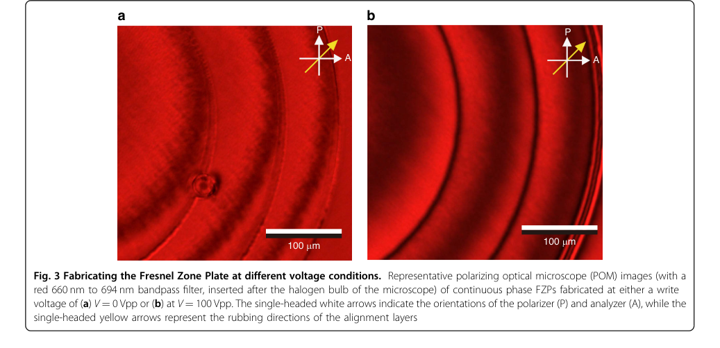 Figure 3. Fabricating the Fresnel Zone Plate at different voltage conditions. Representative polarizing optical microscope (POM) images (with a red 660 nm to 694 nm bandpass filter, inserted after the halogen bulb of the microscope) of continuous phase FZPs fabricated at either a write voltage of (a) V = 0 Vpp or (b) at V = 100 Vpp. The single-headed white arrows indicate the orientations of the polarizer (P) and analyzer (A), while the single-headed yellow arrows represent the rubbing directions of the alignment layers
Mathematical & Logical Mechanism
The Master Equation
The core mathematical engine powering this paper's innovation—an electrically switchable continuous phase liquid crystal Fresnel zone plate (FZP)—is not a single equation but a tightly coupled system. This system describes the ideal optical phase profile, how it's physically realized through a liquid crystal (LC) layer, and how that realization is dynamically controlled by an electric field. The key equations are:
-
Ideal Fresnel Zone Plate Phase Profile: This equation defines the target phase shift required for an ideal FZP to focus light.
$$ \phi(r) = \frac{2\pi}{\lambda} \left(\sqrt{f^2 + r^2} - f\right) $$ -
Optical Phase Difference from Liquid Crystal: This equation quantifies the actual phase shift imparted by the LC layer as light passes through it.
$$ \Delta\phi = \int_0^d \frac{2\pi}{\lambda} n_{eff}(z) dz $$ -
Effective Refractive Index of Nematic Liquid Crystal: This equation describes how the LC's orientation influences the refractive index experienced by light.
$$ n_{eff}(\theta) = \frac{n_o n_e}{\sqrt{n_e^2 \cos^2(\theta) + n_o^2 \sin^2(\theta)}} $$ -
Euler-Lagrange Equation for LC Director Profile: This equation governs the equilibrium orientation of the LC molecules under the influence of elastic forces and an external electric field.
$$ K \frac{d^2\theta}{dz^2} - \epsilon_0 \Delta\epsilon E^2 \sin\theta \cos\theta = 0 $$
Term-by-Term Autopsy
Let's dissect each term in these equations to understand its mathematical definition, physical role, and the author's choice of operators.
Equation 1: Ideal Fresnel Zone Plate Phase Profile
$$ \phi(r) = \frac{2\pi}{\lambda} \left(\sqrt{f^2 + r^2} - f\right) $$
- $\phi(r)$:
1) Mathematical Definition: The phase shift (in radians) introduced by the FZP at a radial distance $r$ from its center.
2) Physical/Logical Role: This term represents the ideal phase retardation profile that an FZP must impose on an incident wavefront to focus light. It's the theoretical blueprint for the lens's optical function.
3) Why this operator: The functional form is derived from the geometric principle that all light rays from a point source (or parallel rays for a collimated beam) should arrive at the focal point in phase. - $2\pi/\lambda$:
1) Mathematical Definition: The wave vector, $k$.
2) Physical/Logical Role: This is a conversion factor that translates a physical optical path length difference (in units of length) into an equivalent phase angle (in radians). It scales the path difference, where $2\pi$ radians corresponds to one full wavelength.
3) Why this operator: Multiplication is used because the phase shift is directly proportional to the optical path length difference. - $\lambda$:
1) Mathematical Definition: The wavelength of light.
2) Physical/Logical Role: This is the specific wavelength of the incident light for which the FZP is designed to operate. It's a fundamental property of the light being manipulated.
3) Why this operator: It's a divisor in the wave vector, indicating that for a given path length difference, shorter wavelengths (smaller $\lambda$) result in larger phase shifts. - $f$:
1) Mathematical Definition: The focal length of the FZP.
2) Physical/Logical Role: This parameter defines the distance from the FZP where incident parallel light rays converge to a single focal point. It dictates the focusing power of the lens.
3) Why this operator: It's a key parameter in the geometric path length calculation. The subtraction of $f$ from the square root term ensures that the phase is zero at the center ($r=0$) and increases outwards, creating the necessary phase profile for focusing. - $r$:
1) Mathematical Definition: The radial coordinate from the lens center.
2) Physical/Logical Role: This variable represents the distance from the optical axis of the FZP. The phase profile of an FZP is radially symmetric, meaning it depends only on $r$, not on the angular position.
3) Why this operator: The FZP is a circularly symmetric diffractive element, so its phase profile naturally depends on the radial distance from the center. - $\sqrt{f^2 + r^2}$:
1) Mathematical Definition: The hypotenuse of a right triangle with sides $f$ and $r$.
2) Physical/Logical Role: This represents the geometric distance from a point on the FZP at radial coordinate $r$ to the focal point located at distance $f$ along the optical axis.
3) Why this operator: This term is derived from the Pythagorean theorem, calculating the distance from a point $(r, 0)$ on the FZP plane to the focal point $(0, f)$ in a cross-section.
Equation 2: Optical Phase Difference from Liquid Crystal
$$ \Delta\phi = \int_0^d \frac{2\pi}{\lambda} n_{eff}(z) dz $$
- $\Delta\phi$:
1) Mathematical Definition: The total optical phase difference (in radians).
2) Physical/Logical Role: This term represents the cumulative phase shift experienced by light as it propagates through the entire thickness of the liquid crystal layer. This is the actual phase retardation achieved by the device.
3) Why this operator: This is the output phase of the LC layer, which needs to match the desired FZP phase profile $\phi(r)$ (after appropriate wrapping). - $\int_0^d \dots dz$:
1) Mathematical Definition: A definite integral over the thickness $d$.
2) Physical/Logical Role: This operator sums up the infinitesimal phase contributions as light travels through the LC layer from $z=0$ to $z=d$. It's used because the effective refractive index $n_{eff}(z)$ can vary continuously along the propagation direction ($z$-axis) within the LC layer.
3) Why this operator: An integral is used instead of a summation because the LC director angle $\theta$ (and thus $n_{eff}$) is assumed to vary continuously across the thickness of the cell, especially in the hybrid aligned nematic (HAN) configuration mentioned in the paper. - $d$:
1) Mathematical Definition: The thickness of the LC layer.
2) Physical/Logical Role: This is the physical extent of the liquid crystal medium through which light propagates.
3) Why this operator: It defines the upper limit of the integration, representing the total path length within the LC material. - $n_{eff}(z)$:
1) Mathematical Definition: The effective refractive index as a function of $z$.
2) Physical/Logical Role: This is the refractive index experienced by the incident light at a specific depth $z$ within the LC layer. It varies with the local orientation of the LC molecules.
3) Why this operator: It's inside the integral because the phase accumulation depends on the refractive index at each point along the path.
Equation 3: Effective Refractive Index of Nematic Liquid Crystal
$$ n_{eff}(\theta) = \frac{n_o n_e}{\sqrt{n_e^2 \cos^2(\theta) + n_o^2 \sin^2(\theta)}} $$
- $n_{eff}(\theta)$:
1) Mathematical Definition: The effective refractive index, dependent on the director angle $\theta$.
2) Physical/Logical Role: This is the refractive index that light "sees" when passing through the birefringent liquid crystal. It is the key to tunable phase modulation, as it changes with the orientation of the LC molecules.
3) Why this operator: This specific form arises from the anisotropic nature of liquid crystals, where the refractive index depends on the polarization of light relative to the molecular orientation. - $n_o$:
1) Mathematical Definition: The ordinary refractive index.
2) Physical/Logical Role: This is the refractive index experienced by light polarized perpendicular to the LC director (optic axis). It's typically the smaller of the two principal refractive indices.
3) Why this operator: It's a fundamental material property of the nematic LC. - $n_e$:
1) Mathematical Definition: The extraordinary refractive index.
2) Physical/Logical Role: This is the refractive index experienced by light polarized parallel to the LC director (optic axis). It's typically the larger of the two principal refractive indices.
3) Why this operator: It's another fundamental material property of the nematic LC. - $\theta$:
1) Mathematical Definition: The director angle with respect to the z-axis (propagation direction).
2) Physical/Logical Role: This is the angle that the long axis of the liquid crystal molecules (the director) makes with the optical axis. This angle is controlled by the applied electric field.
3) Why this operator: It's the variable that dictates the effective refractive index due to the LC's birefringence. - $\cos^2(\theta)$ and $\sin^2(\theta)$:
1) Mathematical Definition: Squared trigonometric functions of the director angle.
2) Physical/Logical Role: These terms represent the projection of the LC director onto the ordinary and extraordinary axes relative to the incident light's polarization and propagation direction. They determine the weighting of $n_o$ and $n_e$ in the effective refractive index.
3) Why this operator: They arise from the tensor nature of the refractive index in anisotropic materials, specifically how the refractive index ellipsoid is oriented relative to the light's polarization. The sum of squares in the denominator is characteristic of how effective refractive index is calculated for uniaxial crystals.
Equation 4: Euler-Lagrange Equation for LC Director Profile
$$ K \frac{d^2\theta}{dz^2} - \epsilon_0 \Delta\epsilon E^2 \sin\theta \cos\theta = 0 $$
- $K$:
1) Mathematical Definition: The Frank elastic constant (using a single elastic constant approximation, representing an average of splay, twist, and bend constants).
2) Physical/Logical Role: A material property representing the liquid crystal's resistance to deformation (bending, twisting, splaying) of its molecular alignment. A higher $K$ means the LC is stiffer and harder to reorient.
3) Why this operator: It's a coefficient in the elastic torque term, determining the strength of the restoring force that tries to maintain the LC's preferred alignment. - $\frac{d^2\theta}{dz^2}$:
1) Mathematical Definition: The second derivative of the director angle $\theta$ with respect to $z$.
2) Physical/Logical Role: This term represents the curvature or spatial variation of the LC director profile along the thickness of the cell. It's directly related to the elastic deformation energy.
3) Why this operator: It's part of the elastic torque term, which arises from minimizing the elastic free energy density of the LC. - $\epsilon_0$:
1) Mathematical Definition: The permittivity of free space.
2) Physical/Logical Role: A fundamental physical constant representing the ability of a vacuum to permit electric fields. It scales the electric field's influence.
3) Why this operator: It's a standard constant in electromagnetism, used to convert electric field strength into energy density. - $\Delta\epsilon$:
1) Mathematical Definition: The dielectric anisotropy ($\epsilon_e - \epsilon_o$).
2) Physical/Logical Role: The difference between the dielectric permittivity parallel ($\epsilon_e$) and perpendicular ($\epsilon_o$) to the LC director. It quantifies how strongly the LC molecules align with an external electric field.
3) Why this operator: It's a material property that determines the strength of the dielectric torque exerted by the electric field on the LC director. - $E$:
1) Mathematical Definition: The applied electric field strength.
2) Physical/Logical Role: The external electric field applied across the LC layer, which exerts a torque on the LC molecules, causing them to reorient. This is the control input for switching the FZP.
3) Why this operator: It's squared because the dielectric torque depends on the energy density of the electric field, which is proportional to $E^2$. - $\sin\theta \cos\theta$:
1) Mathematical Definition: The product of the sine and cosine of the director angle.
2) Physical/Logical Role: This term represents the angular dependence of the dielectric torque. The torque is maximum when $\theta = \pi/4$ (45 degrees) and zero when $\theta = 0$ or $\theta = \pi/2$ (0 or 90 degrees), meaning the LC is fully aligned with or perpendicular to the field.
3) Why this operator: This specific form arises from the calculation of the torque exerted by an electric field on an anisotropic dielectric material. It's a fundamental part of the Euler-Lagrange equation for LC. - $= 0$:
1) Mathematical Definition: Equation set to zero.
2) Physical/Logical Role: This signifies that the system is in equilibrium. The elastic torque (first term) is precisely balanced by the dielectric torque (second term), resulting in a stable director profile.
3) Why this operator: This is the condition for minimizing the total free energy of the LC system, leading to a stable configuration of the director profile.
Step-by-Step Flow
Let's trace the exact lifecycle of an abstract data point, representing a ray of light, as it passes through this electrically switchable continuous phase FZP.
- Desired Phase Profile Blueprint: First, the design process begins by calculating the ideal phase shift $\phi(r)$ that an FZP should impart on an incoming plane wave to focus it at a specific focal length $f$. This is the theoretical target, a continuous phase map across the FZP's aperture, determined by the equation $\phi(r) = \frac{2\pi}{\lambda} \left(\sqrt{f^2 + r^2} - f\right)$. This blueprint guides the physical implementation. The unwrapped phase profile is then wrapped into a 0-2$\pi$ or 0-4$\pi$ range, and the correlation between the optical phase difference ($\Delta\phi$) and the required polymerization height is established using the Euler-Lagrange relaxation method. This allows for the reconstruction of the necessary height profile for the FZP.
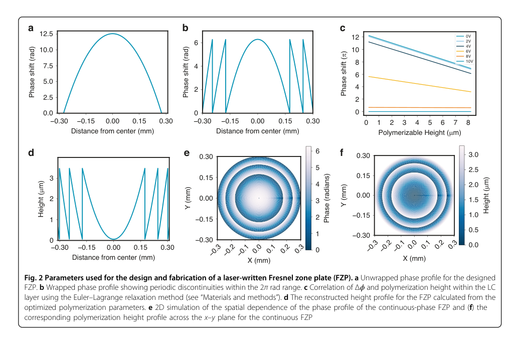 Figure 2. Parameters used for the design and fabrication of a laser-written Fresnel zone plate (FZP). a Unwrapped phase profile for the designed FZP. b Wrapped phase profile showing periodic discontinuities within the 2π rad range. c Correlation of Δϕ and polymerization height within the LC layer using the Euler–Lagrange relaxation method (see “Materials and methods”). d The reconstructed height profile for the FZP calculated from the optimized polymerization parameters. e 2D simulation of the spatial dependence of the phase profile of the continuous-phase FZP and (f) the corresponding polymerization height profile across the x–y plane for the continuous FZP
- LC Director Profile Sculpting (Fabrication): During fabrication, a two-photon polymerization direct laser writing (TPP-DLW) system is used to "sculpt" a polymer network within the liquid crystal. This network locally locks the LC director angle $\theta$ into a specific, spatially varying profile. The Euler-Lagrange equation ($K \frac{d^2\theta}{dz^2} - \epsilon_0 \Delta\epsilon E^2 \sin\theta \cos\theta = 0$) is solved iteratively during the design phase to determine the precise $\theta(z)$ profile needed at each radial position $r$ to achieve the desired $\phi(r)$ after light propagates through the LC. The fabrication process is typically performed under a high voltage (e.g., 100 Vpp) to ensure homeotropic alignment of the LC director, which is then locked into place by the polymerized network. This creates a static "template" for the FZP.
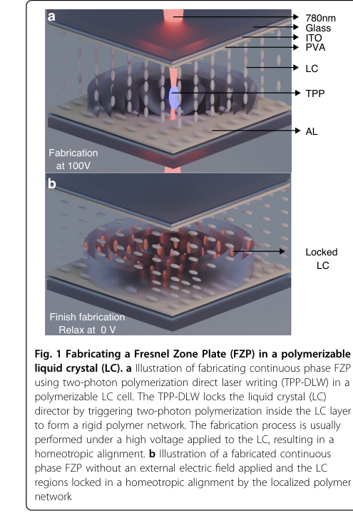 Figure 1. Fabricating a Fresnel Zone Plate (FZP) in a polymerizable liquid crystal (LC). a Illustration of fabricating continuous phase FZP using two-photon polymerization direct laser writing (TPP-DLW) in a polymerizable LC cell. The TPP-DLW locks the liquid crystal (LC) director by triggering two-photon polymerization inside the LC layer to form a rigid polymer network. The fabrication process is usually performed under a high voltage applied to the LC, resulting in a homeotropic alignment. b Illustration of a fabricated continuous phase FZP without an external electric field applied and the LC regions locked in a homeotropic alignment by the localized polymer network
-
Electric Field Application (Switching Input): Once the device is fabricated, an external voltage is applied across the LC cell. This voltage generates an electric field $E$ within the unpolymerized regions of the LC. This field acts as the control input, exerting a dielectric torque on the free-moving LC molecules.
-
LC Molecular Reorientation: In response to the applied electric field $E$, the LC molecules in the unpolymerized regions reorient. This reorientation is governed by the Euler-Lagrange equation, which describes the balance between the elastic forces (trying to maintain a uniform or smooth profile) and the dielectric forces (trying to align the molecules with the electric field). The LC director profile $\theta(z)$ in these regions dynamically changes until a new equilibrium is reached.
-
Effective Refractive Index Modulation: As the LC director angle $\theta(z)$ changes due to reorientation, the effective refractive index $n_{eff}(\theta)$ experienced by the incoming light also changes. This is calculated using $n_{eff}(\theta) = \frac{n_o n_e}{\sqrt{n_e^2 \cos^2(\theta) + n_o^2 \sin^2(\theta)}}$. A higher voltage typically causes $\theta$ to align more with the field, altering $n_{eff}$.
-
Phase Retardation Accumulation: Our abstract light ray, entering the FZP, now encounters this spatially and voltage-dependent effective refractive index $n_{eff}(z)$. As it traverses the LC layer of thickness $d$, it accumulates a total phase shift $\Delta\phi$. This actual phase shift is calculated by integrating $n_{eff}(z)$ along the path: $\Delta\phi = \int_0^d \frac{2\pi}{\lambda} n_{eff}(z) dz$.
-
Focal Length Switching: By carefully selecting the applied voltage $E$, the LC director profile $\theta(z)$ is manipulated such that the resulting $\Delta\phi(r)$ profile matches a specific wrapped FZP phase profile (e.g., a $4\pi$ rad profile for $f=24$ mm at 0 Vpp, or a $2\pi$ rad profile for $f=48$ mm at 2.1 Vpp). This allows the device to switch its focal length or turn its focusing action on/off. The light ray, having acquired this specific phase profile, then converges to the corresponding focal point.
Optimization Dynamics
The "optimization" in this context refers less to an iterative learning algorithm in the traditional sense and more to the careful design, material selection, and fabrication parameter tuning required to achieve the desired optical performance and switchability.
-
Equilibrium via Euler-Lagrange Relaxation: During the design phase, the Euler-Lagrange equation ($K \frac{d^2\theta}{dz^2} - \epsilon_0 \Delta\epsilon E^2 \sin\theta \cos\theta = 0$) is solved using a relaxation method. This iterative process starts with an initial guess for the LC director profile $\theta(z)$ and then repeatedly updates it until the net torque on the LC molecules is zero, meaning the system has reached a stable, minimum-energy configuration. This numerical "optimization" determines the ideal $\theta(z)$ profile for a given electric field and boundary conditions, which then dictates the required polymerization height profile.
-
Material and Fabrication Parameter Tuning: The authors performed extensive empirical optimization of material composition and TPP-DLW parameters. This is akin to shaping the "loss landscape" of the device's performance:
- Reactive Mesogen (RM257) Concentration: A concentration of 20 wt.% or higher was found to be critical. Lower concentrations led to "insufficient network formation" and "inhomogeneities," which would correspond to a high "loss" in terms of phase profile fidelity and increased scattering. Increasing RM257 reduces this "loss" by providing a robust polymer framework.
- Photoinitiator Concentration: 1 wt.% IR819 was chosen to ensure "reliable polymerization." This parameter directly impacts the efficiency and completeness of the polymer network formation, minimizing defects that would degrade optical quality.
- Fabrication Voltage: Writing the polymer network at 100 Vpp resulted in a "much smoother profile" compared to 0 Vpp. This indicates that a high electric field during polymerization helps to stabilize the LC director, leading to a lower "loss" (better fidelity) in the locked phase profile.
- Polymerization Height: The maximum polymerization height was limited to around 7 µm. Exceeding this limit would lead to homeotropic alignment throughout the entire LC layer, causing a complete "failure to control the director profile." This is a critical constraint that defines the viable operating region in the design space.
- TPP-DLW Parameters (Resolution, Speed, Power): These parameters were optimized to provide a "sufficient polymerization dose" while "minimizing overexposure-related feature broadening." This ensures the precise sculpting of the polymer network, which directly impacts the accuracy of the realized phase profile and thus the focusing efficiency and aberration.
-
Voltage-Controlled Switching Dynamics: In operation, the device doesn't "learn" but rather responds dynamically to the applied voltage.
- Gradient-like Torques: The applied electric field $E$ creates a dielectric torque on the LC molecules, acting like a "gradient" that drives the director angle $\theta$ towards alignment with the field. This "driving force" is balanced by the elastic torque, which resists deformation.
- Discrete State Convergence: The LC system settles into distinct equilibrium states (minima in the free energy landscape) corresponding to specific applied voltages (e.g., 0 Vpp for $f=24$ mm, 2.1 Vpp for $f=48$ mm, and 10 Vpp for the OFF state). The paper notes that the device is a "bi-stable (or dual-state) varifocal element," meaning it converges to these well-defined states rather than offering continuous tuning. Intermediate voltages might lead to "mixed-order responses" or "broadened foci," indicating a less optimal state or higher "loss" in terms of focusing quality. The system's response time (rise and fall times) describes how quickly it transitions between these states, with the fall time being much quicker than the rise time due to the interplay of rotational viscosity, elastic constants, and the applied voltage, as described by equations (3) and (4). The optimization here is to ensure these transitions are robust and repeatable over many cycles.
Results, Limitations & Conclusion
Experimental Design & Baselines
The experimental validation of the electrically switchable continuous phase liquid crystal Fresnel zone plates (FZPs) was meticulously designed to demonstrate the efficacy and advantages of the proposed two-photon polymerization direct laser writing (TPP-DLW) approach. The core mechanism involves sculpting a continuous phase profile within a polymerizable nematic liquid crystal (LC) mixture, which is then electrically tunable.
The devices were fabricated within a 20 µm air gap anti-parallel rubbed LC glass cell, filled with a specific polymerizable LC mixture comprising 78 wt.% of the nematic LC E7, 20 wt.% of the reactive mesogen RM257, and 1 wt.% of the photoinitiator IR819. Fabrication was performed using a Spectra-Physics Mai Tai Titanium-Sapphire laser (780 nm, 100 fs pulses, 80 MHz repetition rate) focused by a 0.45 NA objective lens. A key aspect of the fabrication was applying a high voltage (100 Vpp) during the TPP-DLW process to ensure a homeotropic alignment of the LC director, which was then locked into place by the polymerized network.
To rigorously prove their mathematical claims and the practical functionality of the FZPs, the researchers architected several key experiments and baselines:
- Comparison with Binary FZPs: A conventional binary FZP, designed for the same incident wavelength, dimensions, and focal length, was fabricated in the same LC cell at a different location. This served as a direct "victim" baseline to quantify the efficiency improvement of the continuous phase design.
- Two FZP Designs: Two distinct continuous phase FZPs were fabricated: one with a 2π rad wrapped phase profile (600 µm diameter, 30 mm focal length) for ON/OFF switching, and another with a 4π rad wrapped phase profile (1.2 mm diameter, 24 mm focal length) to demonstrate varifocal behavior.
- Multi-modal Characterization:
- Polarized Optical Microscopy (POM): Used to visually confirm the spatially varying phase distribution and the quality of the polymerized regions (Fig. 3, Fig. 4b, Fig. 7a). This provided qualitative evidence that the physical structure matched the design.
- Digital Holographic Microscopy (DHM): Employed for quantitative extraction of the 3D phase map, allowing for direct comparison of the experimentally retrieved phase profiles with simulated ideal profiles (Fig. 4c, Fig. 7b,c). This was crucial for validating the fidelity of the fabricated phase profiles.
- Far-field Focusing Measurements (CCD Camera): A 633 nm He-Ne laser was used to illuminate the FZPs, and a CCD camera captured focal spots at various propagation distances and applied voltages (Fig. 5a, Fig. 8c,d, Fig. 9). This directly assessed the focusing performance, switchability, and varifocal capabilities.
- Imaging Capability Demonstration: A USAF 1951 resolution target was used as an object in an optical imaging system to demonstrate the varifocal FZP's ability to form clear images at different focal lengths (Fig. 10).
- Long-term Stability Test: A photodiode monitored the focused optical power over 24 hours while the FZP was continuously cycled between ON (2.1 Vpp) and OFF (10 Vpp) states. This assessed the device's robustness and electro-optic stability under prolonged operation.
- Numerical Simulations: Extensive simulations of LC director profiles (using Euler-Lagrange equations) and light propagation (using scalar diffraction theory and FFT) were performed. These simulations provided ideal benchmarks for phase profiles (Fig. 2e,f, Fig. 4a, Fig. 7c) and focusing behavior (Fig. 8a,b), allowing for direct comparison with experimental results to validate the underlying mathematical and physical mechanisms.
What the Evidence Proves
The evidence presented in the paper definitively proves several key claims regarding the electrically switchable continuous phase liquid crystal Fresnel zone plates:
- Superior Focusing Efficiency: The continuous phase FZP ruthlessly defeated its binary counterpart in terms of focusing efficiency. Far-field measurements (Fig. 5b) showed that the normalized intensity at the focus of the continuous phase FZP was almost double that of a binary FZP of equal size and focal length, with a measured ratio of approximately 196%. This is undeniable evidence that the continuous phase design effectively concentrates light into a single diffraction order, significantly reducing power distribution to unwanted orders, a critical advantage for high-fidelity optical systems.
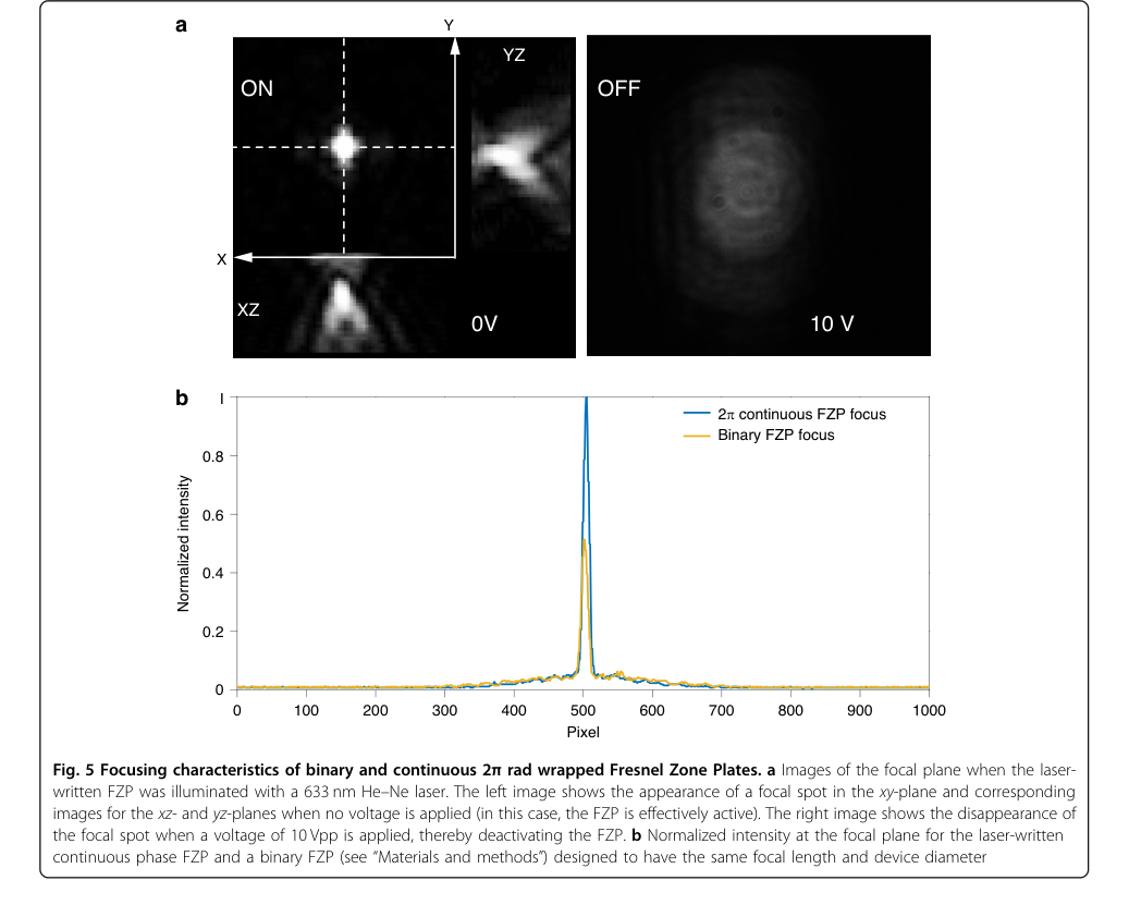 Figure 5. Focusing characteristics of binary and continuous 2π rad wrapped Fresnel Zone Plates. a Images of the focal plane when the laser- written FZP was illuminated with a 633 nm He–Ne laser. The left image shows the appearance of a focal spot in the xy-plane and corresponding images for the xz- and yz-planes when no voltage is applied (in this case, the FZP is effectively active). The right image shows the disappearance of the focal spot when a voltage of 10 Vpp is applied, thereby deactivating the FZP. b Normalized intensity at the focal plane for the laser-written continuous phase FZP and a binary FZP (see “Materials and methods”) designed to have the same focal length and device diameter
- True Electrical ON/OFF Switching: For the 2π rad wrapped FZP, the core mechanism of electrical switchability was clearly demonstrated (Fig. 5a). At 0 Vpp, a bright and sharp focal spot was observed, indicating the FZP was actively focusing light. Crucially, when a voltage of 10 Vpp was applied, the focal spot disappeared, and the far-field image became blurry and dark. This unequivocally proves that the device can be electrically switched OFF, deactivating its focusing functionality, without any mechanical movement.
- Discrete Varifocal Behavior: The 4π rad wrapped FZP demonstrated a novel varifocal capability, switching between two distinct focal lengths. At 0 Vpp, the device produced a sharp focal spot at $f = 24 \text{ mm}$. Upon applying an intermediate voltage of 2.1 Vpp, the focal length effectively doubled, resulting in a clear focus at $f = 48 \text{ mm}$ (Fig. 8c,d and Fig. 9). At higher voltages (e.g., 10 Vpp), the focus disappeared entirely, confirming the OFF state. The imaging experiments with a USAF 1951 target (Fig. 10) further solidified this, showing clear images at both 24 mm (0 Vpp) and 48 mm (2.1 Vpp) focal planes. This demonstrates that the applied voltage can tune the phase profile to achieve different, well-defined focal lengths.
- High Fidelity of Fabricated Phase Profiles: The combination of POM images (Fig. 4a,b, Fig. 7a) and quantitative digital holographic microscopy (Fig. 4c, Fig. 7b,c) confirmed that the fabricated continuous phase profiles closely matched the designed theoretical profiles. This validation of the physical structure against the mathematical design is definitive evidence that the TPP-DLW method successfully sculpts the intended 3D refractive index distribution within the LC layer.
- Long-term Electro-optic Stability: The device exhibited remarkable long-term stability. A 24-hour continuous cycling experiment, involving over $1.4 \times 10^3$ switching events between ON (2.1 Vpp) and OFF (10 Vpp) states, showed no systematic decay or fatigue in the electro-optic response. The average focusing power in the ON state remained nearly constant, with a drift of less than 1% of the mean power, which was attributed to expected laser and detector drift rather than intrinsic device degradation. This proves the robustness of the polymer-stabilized phase profile and LC director configuration under repeated electrical driving.
Limitations & Future Directions
While the presented continuous phase FZPs represent a significant leap forward in reconfigurable diffractive optics, the paper candidly discusses several limitations and proposes clear pathways for future development.
Limitations
- Fabrication Imperfections and Phase Profile Fidelity: Despite the success, the paper acknowledges that small deviations from the ideal height profile can lead to residual light leakage and slight focal broadening. These imperfections stem from three main sources:
- Substrate Tilt: An unintended linear phase ramp across the aperture due to residual substrate tilt during laser writing.
- LC Non-uniformity: LC relaxation and director non-uniformity, particularly at intermediate voltages, cause local birefringence variations.
- Voxel Size and Sampling: The finite voxel size and limited sampling of the outer Fresnel zones constrain the fidelity of the realized 4π profile.
Additionally, writing at 0 Vpp, while desirable for some applications, led to "fuzzy and less stable polymer microstructures" due to thermal fluctuations and increased susceptibility of the LC director to random motion. The measured phase profile for the 4π FZP was found to be around 11 rad instead of the ideal 4π (approximately 12.56 rad), contributing to slight mismatches and blurry spots.
- Switching Speed: The device's response time, particularly the rise time, is relatively slow. The measured rise time was 6.734 s, while the fall time was quicker at 0.245 s. This slowness is attributed to:
- Fabrication Voltage: FZPs fabricated at 100 Vpp (high voltage) lock the LC into a homeotropically aligned state, making switching from high to low voltage states inherently slower.
- Hybrid Aligned Nematic (HAN) Configuration: This configuration introduces competing boundary conditions, leading to a non-uniform hybrid director profile and slower apparent switching times due to anchoring-constrained profile reconstruction.
- LC Layer Thickness: The 20 µm LC layer is relatively thick, and as the rise time is proportional to the square of the LC layer thickness ($T_{rise} \sim \frac{\gamma_1 d^2}{\pi^2 K}$), this significantly impedes fast switching.
- Discrete Varifocal Operation: The device is engineered as a bi-stable (or dual-state) varifocal element, switching between two well-defined focal planes, rather than offering a continuously tunable focal length. Intermediate voltages between these operating points can lead to mixed-order responses, distributing optical power across multiple diffraction orders and resulting in broadened or partially overlapping foci.
- Scalability for Large Apertures: Direct TPP-DLW for fabricating centimeter-scale monolithic apertures remains a challenge due to the intrinsic slow voxel-by-voxel writing process and limited field of view. The current devices are demonstrated at a millimeter scale.
Future Directions
The findings open up exciting avenues for future research and development, aiming to address current limitations and expand functionality:
- Enhancing Fabrication Accuracy and Phase Fidelity:
- Improved Tilt Control: Implementing better mechanical tip-tilt control during writing and numerically pre-compensating the design with a corrective linear phase term could mitigate substrate tilt issues.
- Advanced Writing Parameters: Utilizing higher numerical aperture (NA) objectives to generate smaller voxel sizes and finer writing grids, along with wavefront-corrected exposure (e.g., SLM-based aberration compensation), can improve fabrication accuracy and the fidelity of the 4π profile.
- Temperature Control during Fabrication: To overcome the issues of fuzzy and less stable polymer microstructures when writing at 0 Vpp, active temperature control (e.g., using a cooling stage) during laser fabrication could stabilize the LC director and suppress thermally driven pattern blurring.
- Improving Switching Speed and Robustness:
- Optimized Device Architecture: Future work will focus on optimizing writing conditions and device architecture to avoid HAN-like configurations and preserve conventional planar nematic alignment. Laser writing at 0 Vpp, coupled with temperature control, is a promising approach.
- Thinner LC Layers: Employing higher NA objectives to reduce the z-voxel size will enable the use of thinner LC layers, which is crucial for achieving faster electro-optic responses, as switching time scales quadratically with thickness.
- Photoinitiator Alternatives: Replacing the photoinitiator IR819 with alternatives less susceptible to ambient light conditions (e.g., IR651) could lead to longer-term stability, especially in the presence of ambient white light.
- Expanding Functionality and Spectral Range:
- Broader Spectral Tunability: Exploring alternative LC formulations could enable broader spectral tunability for the FZPs.
- Higher Phase Wrapping: By using higher birefringence LC materials and higher NA objectives, achieving 6π rad or even 8π rad wrapping within 20 µm LC layer thicknesses is feasible, leading to enhanced switchability and potentially more focal states.
- Stacked LC Layers: Stacking multiple LC layers with higher wrapping FZPs could allow for switching the focal length over a larger number of orders, significantly increasing the device's versatility.
- Scalability for Large-Area Applications:
- Parallelization: To overcome the serial nature of TPP-DLW, parallelization techniques, such as holographic beam splitting or interference-based exposure to create multiple voxels simultaneously, could significantly decrease fabrication time and enable centimeter-scale optical elements.
- Master Fabrication and Replication: The TPP-DLW method could be utilized as a high-precision master fabrication platform to generate a single continuous phase template with nanometric surface fidelity. This master could then be transferred to a nickel shim via electro-forming and replicated at wafer-level throughput using UV nanoimprint lithography, providing a realistic route to large-area, high-volume production.
These future developments will further solidify the role of continuous phase LC FZPs in next-generation lightweight, power-efficient, and high-performance optical systems, particularly for applications in augmented and virtual reality, adaptive optics, and compact imaging systems.
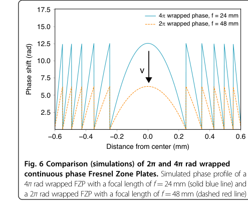 Figure 6. Comparison (simulations) of 2π and 4π rad wrapped continuous phase Fresnel Zone Plates. Simulated phase profile of a 4π rad wrapped FZP with a focal length of f = 24 mm (solid blue line) and a 2π rad wrapped FZP with a focal length of f = 48 mm (dashed red line)
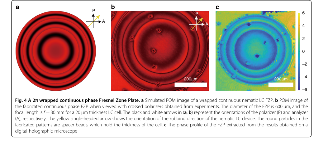 Figure 4. A 2π wrapped continuous phase Fresnel Zone Plate. a Simulated POM image of a wrapped continuous nematic LC FZP. b POM image of the fabricated continuous phase FZP when viewed with crossed polarizers obtained from experiments. The diameter of the FZP is 600 µm, and the focal length is f = 30 mm for a 20 µm thickness LC cell. The black and white arrows in (a, b) represent the orientations of the polarizer (P) and analyzer (A), respectively. The yellow single-headed arrow shows the orientation of the rubbing direction of the nematic LC device. The round particles in the fabricated patterns are spacer beads, which hold the thickness of the cell. c The phase profile of the FZP extracted from the results obtained on a digital holographic microscope
Connections to Other Fields
Mathematical Skeleton
The pure mathematical core involves the design of a radially symmetric phase function for wavefront manipulation, its dynamic modification through the solution of a continuum mechanics problem (Euler-Lagrange equation for anisotropic media under external fields), and the simulation of light propagation using Fourier optics, a well-establised field.
Adjacent Research Areas
Diffractive Optics
The core concept of a Fresnel Zone Plate (FZP), defined by its phase profile $\phi(r) = \frac{2\pi}{\lambda} \left( \sqrt{f^2 + r^2} - f \right)$, is a fundamental component of diffractive optics. The paper extends this by creating a continuous, rather than binary, phase profile for improved efficiency and by making it electrically switchable. The scalar diffraction theory, particularly the Fresnel approximation and Fast Fourier Transform (FFT)-based propagation, used to model light propagation through the FZP, is a standard computational tool in this field.
(Goodman, J. W. Introduction to Fourier Optics, 2017, MacMillan Learning)
Adaptive Optics and Spatial Light Modulators
The paper's ability to electrically switch the focal length and turn the lens functionality ON/OFF directly connects to the principles of adaptive optics, a feild focused on dynamic wavefront correction. The dynamic control of the optical phase profile by reorienting liquid crystal molecules with an applied electric field is the operational mechanism of many liquid crystal spatial light modulators (LC-SLMs). The Euler-Lagrange equation, $K \frac{d^2\theta}{dz^2} - \epsilon_0 \Delta\epsilon E^2 \sin\theta \cos\theta = 0$, which describes the LC director's response to the electric field, is central to understanding and designing such adaptive elements.
(Naumov, A. F. et al. Liquid-crystal adaptive lenses with modal control, 1998, Opt. Lett.)
Soft Matter Physics (Liquid Crystal Theory)
The fundamental physics governing the behavior of the liquid crystal material itself, particularly its anisotropic optical properties and its response to external electric fields, is a core area of soft matter physics. The Euler-Lagrange equation, which models the balance between elastic forces (due to molecular alignment) and electric torques, is a cornerstone of continuum theory for liquid crystals. Understanding the material parameters like elastic constants ($K$), dielectric anisotropy ($\Delta\epsilon$), and rotational viscosity ($\gamma_1$) is crucial for predicting and controlling the device's optical performance and switching speeed.
(Andrienko, D. Introduction to liquid crystals, 2018, J. Mol. Liq.)