Power-efficient ultra-broadband soliton microcombs in resonantly-coupled microresonators
The drive to miniaturize optical frequency combs for practical deployment has spotlighted microresonator solitons as a promising chip-scale candidate.
Background & Academic Lineage
The Origin & Academic Lineage
The precise origin of the problem addressed in this paper stems from the ongoing drive to transition advanced optical frequency combs from specialized laboratory settings into practical, real-world applications. For nearly two decades since their invention, optical frequency combs have been revolutionary tools, but their widespread deployment has been hindered by their size and power consumption. The academic field, particularly in integrated photonics, has thus been focused on miniaturizing these devices, leading to the spotlight on soliton microcombs as a promising chip-scale solution.
However, a fundamental limitation, or "pain point," of previous approaches became apparent: these chip-scale soliton microcombs were often very power-hungry, especially when researchers aimed for broader spectral spans (like octave-spanning combs) or finer comb spacings, which are crucial for many applications. The paper explicitly states that achieving an octave-spanning comb at microwave repetition rates for direct optical-microwave linkage was considered "not possible for photonic integration due to the high power requirements." The conventional architecture, where a nonlinear microresonator is directly coupled to a bus waveguide, requires the input pump power ($P_{in}$) to exceed a certain threshold ($P_{th}$) to initiate four-wave mixing and even more power for stable soliton formation. This led to a significant "pump-power bottleneck," preventing the realization of compact, power-efficient, and broadband microcombs. The authors were compelled to write this paper to overcome this bottleneck, which they refer to as the "impossible trinity" – the inability to simultaneously optimize comb span, power, and spacing under limited pump power, particularly due to a quadratic scaling law that makes increasing bandwidth or reducing repetition rate extremely power-intensive.
The core limitation of traditional approaches is encapsulated in what the authors term the "impossible trinity" of soliton microcombs (Fig. 1b).
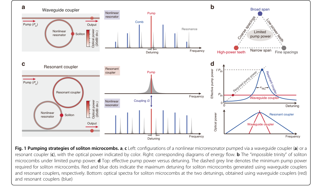 Figure 1. Pumping strategies of soliton microcombs. a, c Left: configurations of a nonlinear microresonator pumped via a waveguide coupler (a) or a resonant coupler (c), with the optical power indicated by color. Right: corresponding diagrams of energy flow. b The “impossible trinity” of soliton microcombs under limited pump power. d Top: effective pump power versus detuning. The dashed grey line denotes the minimum pump power required for soliton microcombs. Red and blue dots indicate the maximum detuning for soliton microcombs generated using waveguide couplers and resonant couplers, respectively. Bottom: optical spectra for soliton microcombs at the two detunings, obtained using waveguide couplers (red) and resonant couplers (blue)
This concept highlights that under limited pump power, it is impossible to simultaneously optimize the comb's spectral span, output power, and repetition rate.
Intuitive Domain Terms
- Optical Frequency Comb: Imagine a super-precise ruler, but instead of measuring length, it measures light frequencies. This ruler has perfectly evenly spaced "teeth" (like a hair comb) that are made of light at specific, very stable frequencies. These teeth act as reference points, allowing scientists to measure other light sources with extreme accuracy or to create very precise timing signals.
- Soliton Microcomb: Think of a perfectly stable, self-sustaining wave of light, like a solitary ocean wave that travels across the sea without changing its shape. Now, imagine this light wave trapped and circulating within a tiny, highly efficient optical loop (a microresonator). This stability comes from a delicate balance of forces within the light itself. When this stable light wave is repeatedly generated, it creates the "teeth" of the optical frequency comb.
- Microresonator: This is essentially a miniature, high-quality racetrack for light. Light enters this tiny ring or disk and circulates many, many times, building up its intensity. The "high-Q" (high quality factor) means the light loses very little energy with each lap, allowing for strong interactions between the light and the material, which is essential for generating the comb.
- Octave-spanning: In music, an octave means doubling a note's frequency (e.g., middle C to high C). In the context of an optical comb, "octave-spanning" means the range of frequencies covered by the comb is so vast that the highest frequency is at least double the lowest frequency. This extremely broad coverage is vital for advanced applications, such as self-referencing, which is like having an absolute, built-in frequency standard for the comb itself.
- Resonant-coupling: This is like adding a turbocharger to the light delivery system. Instead of directly injecting light into the main "racetrack" (the nonlinear microresonator), you first send it into a smaller, auxiliary "booster" resonator. This booster is specifically tuned to resonate with the incoming light, effectively amplifying and concentrating the pump power before it's efficiently transferred to the main resonator. This makes the entire process of generating a soliton microcomb much more power-efficient.
Notation Table
| Notation | Description | Type |
|---|---|---|
| $P_{in}$ | Input pump power | Variable |
| $\Delta f_{3dB}$ | 3-dB bandwidth of the optical frequency comb | Variable |
| $P_c$ | Central-tooth power of the optical frequency comb | Variable |
| $f_r$ | Repetition rate of the optical frequency comb | Variable |
| $\delta\omega$ | Pump-Nonlinear Resonator (NR) detuning | Variable |
| $\kappa_{NR}$ | Total dissipation rate of the Nonlinear Resonator | Parameter |
| $\kappa_{RC}$ | Total dissipation rate of the Resonant Coupler | Parameter |
| $G$ | Coupling rate between the Resonant Coupler (RC) and Nonlinear Resonator (NR) | Parameter |
| $\Gamma$ | Effective pump power enhancement factor due to resonant coupling | Parameter |
Problem Definition & Constraints
Core Problem Formulation & The Dilemma
The central challenge addressed by this paper is the inherent difficulty in generating power-efficient ultra-broadband soliton microcombs suitable for practical, chip-scale deployment.
Input/Current State:
The current state involves conventional soliton microcombs, which are generated in high-quality (high-Q) nonlinear microresonators (NRs) pumped by continuous-wave lasers. These systems rely on a delicate balance between Kerr nonlinearity and anomalous dispersion to produce phase-coherent pulse trains. Key performance metrics for these combs are their spectral span (bandwidth), the power of individual comb teeth, and the repetition rate (spacing between teeth). In conventional waveguide-coupled architectures, stable soliton formation requires the input pump power ($P_{in}$) to exceed a certain threshold ($P_{th}$), and additional power is needed for a red-detuned pump.
Desired Endpoint/Goal State:
The ultimate goal is to achieve octave-spanning (extremely broad bandwidth) soliton microcombs at microwave repetition rates with significantly reduced pump consumption. This would overcome the "long-standing pump-power bottleneck" that has hindered the miniaturization and widespread adoption of microcombs. Such power-efficient, compact devices are crucial for applications like portable optical clocks, massively parallel data links, and field-deployable spectrometers.
Missing Link & Mathematical Gap:
The exact missing link is a mechanism to efficiently deliver and enhance pump power to the nonlinear microresonator, thereby circumventing the high power requirements that scale unfavorably with desired comb characteristics. The paper highlights this through the "impossible trinity" and the governing constraint for conventional microcombs:
$$ P_c \Delta f_{3dB}^2 / f_r < 3.1 \times \eta_{NR} P_{in} $$
Here, $P_c$ is the central-tooth power, $\Delta f_{3dB}$ is the 3-dB bandwidth (spectral span), $f_r$ is the repetition rate, and $\eta_{NR}$ is the loading factor of the NR. This equation reveals a critical mathematical gap: achieving a broader bandwidth ($\Delta f_{3dB}$) or a lower repetition rate ($f_r$) demands substantially higher pump power ($P_{in}$), with a particularly harsh quadratic scaling for bandwidth. This quadratic scaling makes it exceedingly difficult to achieve octave-spanning combs at microwave repetition rates without an impractical amount of pump power. The paper aims to bridge this gap by introducing a resonant-coupling architecture that effectively enhances the pump power delivered to the NR.
The Dilemma (Painful Trade-off):
The core dilemma, termed the "impossible trinity" by the authors (Fig. 1b), is that simultaneously optimizing the three key performance metrics—broad spectral span, high-power comb teeth, and fine comb spacing—is exceedingly difficult under limited pump power.
Figure 1. Pumping strategies of soliton microcombs. a, c Left: configurations of a nonlinear microresonator pumped via a waveguide coupler (a) or a resonant coupler (c), with the optical power indicated by color. Right: corresponding diagrams of energy flow. b The “impossible trinity” of soliton microcombs under limited pump power. d Top: effective pump power versus detuning. The dashed grey line denotes the minimum pump power required for soliton microcombs. Red and blue dots indicate the maximum detuning for soliton microcombs generated using waveguide couplers and resonant couplers, respectively. Bottom: optical spectra for soliton microcombs at the two detunings, obtained using waveguide couplers (red) and resonant couplers (blue)
Improving one aspect typically degrades another or demands an exponential increase in pump power. For instance, achieving a broader spectral span or a finer comb spacing (lower repetition rate) in conventional systems requires disproportionately more pump power, making octave-spanning combs at microwave rates "not possible for photonic integration due to the high power requirements." This trade-off has trapped previous researchers, as any attempt to push the boundaries of bandwidth or repetition rate quickly runs into the wall of prohibitive power consumption.
Constraints & Failure Modes
The problem of generating power-efficient, ultra-broadband soliton microcombs is insanely difficult due to several harsh, realistic constraints:
- Extreme Pump Power Requirements: The most significant constraint is the high optical pump power required for conventional microcombs to achieve broad spectral spans and low repetition rates. As indicated by the quadratic scaling law (Eq. 1), increasing bandwidth or reducing repetition rate demands exponentially more power. For example, the paper extrapolates that matching the resonant coupler's performance at 125 mW and 290 mW pump power would require over 1.5 W and 2 W, respectively, for a waveguide-coupled device (Fig. 2h).
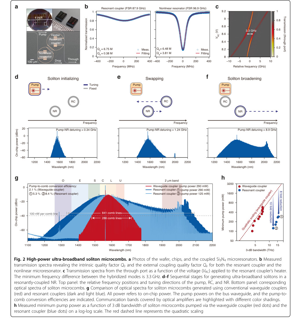 Figure 2. High-power ultra-broadband soliton microcombs. a Photos of the wafer, chips, and the coupled Si3N4 microresonators. b Measured transmission spectra revealing the intrinsic quality factor Q0 and the external coupling quality factor Qe for both the resonant coupler and the nonlinear microresonator. c Transmission spectra from the through port as a function of the voltage (VRC) applied to the resonant coupler’s heater. The minimum frequency difference between the hybridized modes is 3.3 GHz. d–f Sequential stages for generating ultra-broadband solitons in a resonantly-coupled NR. Top panel: the relative frequency positions and tuning directions of the pump, RC, and NR. Bottom panel: corresponding optical spectra of soliton microcombs. g Comparison of optical spectra for soliton microcombs generated using conventional waveguide couplers (red) and resonant couplers (dark and light blue). All power refers to on-chip power. The pump powers on the bus waveguide, and the pump-to- comb conversion efficiencies are indicated. Communication bands covered by optical amplifiers are highlighted with different color shadings. h Measured minimum pump power as a function of 3 dB bandwidth of soliton microcombs pumped via the waveguide coupler (red dots) and the resonant coupler (blue dots) on a log-log scale. The red dashed line represents the quadratic scaling
This is a major barrier for chip-scale integration.
2. Limited On-Chip Laser Power: Practical on-chip lasers, which are essential for miniaturization, typically provide limited optical power. This fundamental hardware memory limit makes it challenging to meet the high pump power demands of conventional microcombs, thus preventing their integration into portable devices.
3. Complex Dispersion Management: Soliton formation relies on a precise balance between Kerr nonlinearity and anomalous group-velocity dispersion (GVD). Achieving ultra-broadband, octave-spanning combs necessitates careful engineering of the microresonator's GVD. Higher-order dispersion and nonlinear effects like Raman self-frequency shifts can limit the maximum achievable comb span and must be meticulously balanced, adding significant design complexity.
4. Mode Interaction and Instability:
* Avoided Mode Crossings: At certain detunings, interactions between the modes of the nonlinear resonator (NR) and the resonant coupler (RC) can lead to "spectral spurs" and irregularities in the comb spectrum (Fig. 2d). While larger detuning can mitigate this, it introduces other issues.
* Modulational Instability: Pushing the detuning too far to broaden the comb can induce modulational instability in the resonant coupler, which in turn destabilizes the soliton itself. This sets a practical limit on the maximum accessible detuning and, consequently, the maximum comb span.
5. Fabrication Precision and Tolerances: Realizing the resonant-coupling architecture requires extremely precise control over the physical parameters of both the RC and NR. This includes their intrinsic and coupling quality factors, as well as their inter-resonator coupling rate. Achieving the desired generalized critical-coupling condition and minimizing direct pump transmission through the bus waveguide demands tight manufacturing tolerances in the Si3N4 fabrication process.
6. Parasitic Effects and Power Leakage:
* Unwanted Parametric Oscillations: The resonant coupler itself can suffer from unwanted parametric oscillations, which must be suppressed (e.g., by engineering its dissipation rate).
* Parasitic Mode Coupling: Unintended coupling between non-pumped resonances can cause comb power to leak from the NR to the RC and then out through the through port, reducing the overall conversion efficiency.
7. Turnkey Operation Challenges: For practical "turnkey" operation with on-chip lasers, phenomena like self-injection locking (where backscattered light re-enters the laser) can perturb laser tuning. While this can be leveraged, it requires precise adjustment of the feedback phase, often via external mechanisms like piezoelectric stages, adding to the system's complexity and reducing its robustness.
Why This Approach
The Inevitability of the Choice
The adoption of the resonantly-coupled microresonator (RC) architecture was not merely an incremental improvement but a fundamental necessity to overcome a critical bottleneck in soliton microcomb technology. The authors explicitly identify that achieving "octave-spanning comb at microwave repetition rates for direct optical-microwave linkage is considered not possible for photonic integration due to the high power requirements" when relying on traditional waveguide-coupled designs. This statement marks the precise moment of realization that conventional state-of-the-art (SOTA) methods were insufficient.
The core limitation of traditional approaches is encapsulated in what the authors term the "impossible trinity" of soliton microcombs (Fig. 1b).
Figure 1. Pumping strategies of soliton microcombs. a, c Left: configurations of a nonlinear microresonator pumped via a waveguide coupler (a) or a resonant coupler (c), with the optical power indicated by color. Right: corresponding diagrams of energy flow. b The “impossible trinity” of soliton microcombs under limited pump power. d Top: effective pump power versus detuning. The dashed grey line denotes the minimum pump power required for soliton microcombs. Red and blue dots indicate the maximum detuning for soliton microcombs generated using waveguide couplers and resonant couplers, respectively. Bottom: optical spectra for soliton microcombs at the two detunings, obtained using waveguide couplers (red) and resonant couplers (blue)
This concept highlights that under limited pump power, it is impossible to simultaneously optimize the comb's spectral span, output power, and repetition rate. The governing equation, $P_c \Delta f_{3dB}^2 / f_r < 3.1 \times \eta_{NR} P_{in}$ (Eq. 9), clearly illustrates a quadratic scaling law, making it exponentially harder to increase bandwidth or reduce repetition rate compared to simply boosting tooth power. Conventional methods, lacking an efficient pump delivery mechanism, were fundamentally constrained by this power-hungry nature, rendering the ambitious goals of octave-spanning, low-repetition-rate, and chip-scale integration unattainable. The RC architecture emerged as the only viable solution capable of fundamentally altering this power dynamic.
Comparative Superiority
The resonant-coupling approach offers a qualitative and structural advantage that makes it overwhelmingly superior to previous gold standards, primarily by addressing the pump-power bottleneck. Structurally, the method interposes an auxiliary microresonator (the RC) between the bus waveguide and the nonlinear resonator (NR). This seemingly simple addition provides a "resonant enhancement of the pump power" delivered to the NR, quantified by an enhancement factor $\Gamma = 4G^2 / (K_{RC} K_{NR})$ (Eq. 2).
This resonant enhancement is not just a minor boost; it's a game-changer. It allows the system to access significantly larger detunings (Fig. 1d),
Figure 1. Pumping strategies of soliton microcombs. a, c Left: configurations of a nonlinear microresonator pumped via a waveguide coupler (a) or a resonant coupler (c), with the optical power indicated by color. Right: corresponding diagrams of energy flow. b The “impossible trinity” of soliton microcombs under limited pump power. d Top: effective pump power versus detuning. The dashed grey line denotes the minimum pump power required for soliton microcombs. Red and blue dots indicate the maximum detuning for soliton microcombs generated using waveguide couplers and resonant couplers, respectively. Bottom: optical spectra for soliton microcombs at the two detunings, obtained using waveguide couplers (red) and resonant couplers (blue)
which in turn "dramatically increases the soliton span" as it scales with $\sqrt{\delta\omega}$. The paper demonstrates a "threefold increase in spectral span for high-power combs and (ii) up to a tenfold reduction in repetition frequency for octave-spanning operation" compared to conventional waveguide-coupled designs. More strikingly, the RC architecture achieves an "up to 10-fold pump power enhancement" (Fig. 2h)
Figure 2. High-power ultra-broadband soliton microcombs. a Photos of the wafer, chips, and the coupled Si3N4 microresonators. b Measured transmission spectra revealing the intrinsic quality factor Q0 and the external coupling quality factor Qe for both the resonant coupler and the nonlinear microresonator. c Transmission spectra from the through port as a function of the voltage (VRC) applied to the resonant coupler’s heater. The minimum frequency difference between the hybridized modes is 3.3 GHz. d–f Sequential stages for generating ultra-broadband solitons in a resonantly-coupled NR. Top panel: the relative frequency positions and tuning directions of the pump, RC, and NR. Bottom panel: corresponding optical spectra of soliton microcombs. g Comparison of optical spectra for soliton microcombs generated using conventional waveguide couplers (red) and resonant couplers (dark and light blue). All power refers to on-chip power. The pump powers on the bus waveguide, and the pump-to- comb conversion efficiencies are indicated. Communication bands covered by optical amplifiers are highlighted with different color shadings. h Measured minimum pump power as a function of 3 dB bandwidth of soliton microcombs pumped via the waveguide coupler (red dots) and the resonant coupler (blue dots) on a log-log scale. The red dashed line represents the quadratic scaling
for a given bandwidth. When comparing the figure of merit $P_{in} \times f_r^2$ for octave-spanning comb generation, the RC architecture achieves values around $10^5 \text{ mW} \cdot \text{GHz}^2$, which is "lower than the best results reported in conventional waveguide-coupled configurations by two orders of magnitude" (Fig. 3f).
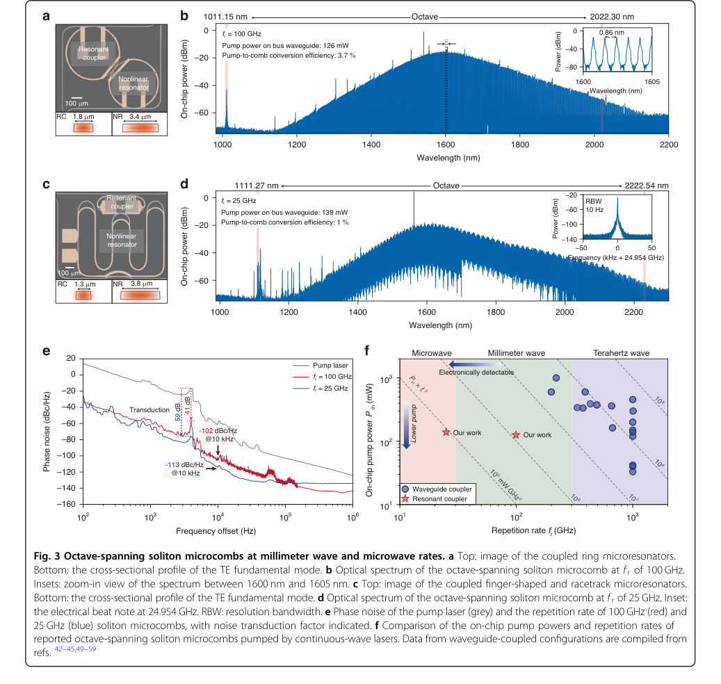 Figure 3. Octave-spanning soliton microcombs at millimeter wave and microwave rates. a Top: image of the coupled ring microresonators. Bottom: the cross-sectional profile of the TE fundamental mode. b Optical spectrum of the octave-spanning soliton microcomb at f r of 100 GHz. Insets: zoom-in view of the spectrum between 1600 nm and 1605 nm. c Top: image of the coupled finger-shaped and racetrack microresonators. Bottom: the cross-sectional profile of the TE fundamental mode. d Optical spectrum of the octave-spanning soliton microcomb at f r of 25 GHz. Inset: the electrical beat note at 24.954 GHz. RBW: resolution bandwidth. e Phase noise of the pump laser (grey) and the repetition rate of 100 GHz (red) and 25 GHz (blue) soliton microcombs, with noise transduction factor indicated. f Comparison of the on-chip pump powers and repetition rates of reported octave-spanning soliton microcombs pumped by continuous-wave lasers. Data from waveguide-coupled configurations are compiled from refs. 42–45,49–59
This represents a profound qualitative leap in power efficiency, enabling performance previously deemed impossible.
While the paper does not discuss memory complexity or high-dimensional noise handling in the context of typical machine learning algorithms, it does characterize the phase noise of the generated combs (Fig. 3e). The results show phase noise comparable to the lowest reported for free-running integrated soliton microcombs, indicating that the resonant coupling does not introduce detrimental noise characteristics and maintains high coherence, which is crucial for applications like optical clocks. The primary superiority lies in its ability to break the power-bandwidth-repetition rate trade-off.
Alignment with Constraints
The chosen resonant-coupling method perfectly aligns with the stringent constraints of the problem, forming a true "marriage" between the harsh requirements and the solution's unique properties.
- Miniaturization and Chip-Scale Deployment: The entire architecture, including the RC and NR, is fabricated on a Si3N4 chip (Fig. 2a),
Figure 2. High-power ultra-broadband soliton microcombs. a Photos of the wafer, chips, and the coupled Si3N4 microresonators. b Measured transmission spectra revealing the intrinsic quality factor Q0 and the external coupling quality factor Qe for both the resonant coupler and the nonlinear microresonator. c Transmission spectra from the through port as a function of the voltage (VRC) applied to the resonant coupler’s heater. The minimum frequency difference between the hybridized modes is 3.3 GHz. d–f Sequential stages for generating ultra-broadband solitons in a resonantly-coupled NR. Top panel: the relative frequency positions and tuning directions of the pump, RC, and NR. Bottom panel: corresponding optical spectra of soliton microcombs. g Comparison of optical spectra for soliton microcombs generated using conventional waveguide couplers (red) and resonant couplers (dark and light blue). All power refers to on-chip power. The pump powers on the bus waveguide, and the pump-to- comb conversion efficiencies are indicated. Communication bands covered by optical amplifiers are highlighted with different color shadings. h Measured minimum pump power as a function of 3 dB bandwidth of soliton microcombs pumped via the waveguide coupler (red dots) and the resonant coupler (blue dots) on a log-log scale. The red dashed line represents the quadratic scaling
directly meeting the demand for a compact, integrated solution.
2. Octave-Spanning Bandwidth: The resonant enhancement of pump power allows for significantly larger detunings, which directly translates to a "dramatically increased soliton span" (Fig. 1d).
Figure 1. Pumping strategies of soliton microcombs. a, c Left: configurations of a nonlinear microresonator pumped via a waveguide coupler (a) or a resonant coupler (c), with the optical power indicated by color. Right: corresponding diagrams of energy flow. b The “impossible trinity” of soliton microcombs under limited pump power. d Top: effective pump power versus detuning. The dashed grey line denotes the minimum pump power required for soliton microcombs. Red and blue dots indicate the maximum detuning for soliton microcombs generated using waveguide couplers and resonant couplers, respectively. Bottom: optical spectra for soliton microcombs at the two detunings, obtained using waveguide couplers (red) and resonant couplers (blue)
This enables the generation of octave-spanning microcombs, as demonstrated with spans from 1007 to 2130 nm (Fig. 3b) and 1098 to 2250 nm (Fig. 3d).
Figure 3. Octave-spanning soliton microcombs at millimeter wave and microwave rates. a Top: image of the coupled ring microresonators. Bottom: the cross-sectional profile of the TE fundamental mode. b Optical spectrum of the octave-spanning soliton microcomb at f r of 100 GHz. Insets: zoom-in view of the spectrum between 1600 nm and 1605 nm. c Top: image of the coupled finger-shaped and racetrack microresonators. Bottom: the cross-sectional profile of the TE fundamental mode. d Optical spectrum of the octave-spanning soliton microcomb at f r of 25 GHz. Inset: the electrical beat note at 24.954 GHz. RBW: resolution bandwidth. e Phase noise of the pump laser (grey) and the repetition rate of 100 GHz (red) and 25 GHz (blue) soliton microcombs, with noise transduction factor indicated. f Comparison of the on-chip pump powers and repetition rates of reported octave-spanning soliton microcombs pumped by continuous-wave lasers. Data from waveguide-coupled configurations are compiled from refs. 42–45,49–59
- Microwave Repetition Rates: By overcoming the power bottleneck, the RC architecture facilitates the generation of combs with repetition rates in the microwave regime, such as 100 GHz and 25 GHz (Fig. 3b, d, e),
Figure 3. Octave-spanning soliton microcombs at millimeter wave and microwave rates. a Top: image of the coupled ring microresonators. Bottom: the cross-sectional profile of the TE fundamental mode. b Optical spectrum of the octave-spanning soliton microcomb at f r of 100 GHz. Insets: zoom-in view of the spectrum between 1600 nm and 1605 nm. c Top: image of the coupled finger-shaped and racetrack microresonators. Bottom: the cross-sectional profile of the TE fundamental mode. d Optical spectrum of the octave-spanning soliton microcomb at f r of 25 GHz. Inset: the electrical beat note at 24.954 GHz. RBW: resolution bandwidth. e Phase noise of the pump laser (grey) and the repetition rate of 100 GHz (red) and 25 GHz (blue) soliton microcombs, with noise transduction factor indicated. f Comparison of the on-chip pump powers and repetition rates of reported octave-spanning soliton microcombs pumped by continuous-wave lasers. Data from waveguide-coupled configurations are compiled from refs. 42–45,49–59
which are electronically detectable.
4. Low Pump Power / Power Efficiency: This is where the alignment is most striking. The RC's unique property of resonantly enhancing pump delivery directly tackles the "long-standing pump-power bottleneck." The method achieves octave-spanning combs with substantially lower pump powers, demonstrating a 10-fold reduction in pump power for comparable bandwidths and two orders of magnitude improvement in the $P_{in} \times f_r^2$ figure of merit (Fig. 3f).
Figure 3. Octave-spanning soliton microcombs at millimeter wave and microwave rates. a Top: image of the coupled ring microresonators. Bottom: the cross-sectional profile of the TE fundamental mode. b Optical spectrum of the octave-spanning soliton microcomb at f r of 100 GHz. Insets: zoom-in view of the spectrum between 1600 nm and 1605 nm. c Top: image of the coupled finger-shaped and racetrack microresonators. Bottom: the cross-sectional profile of the TE fundamental mode. d Optical spectrum of the octave-spanning soliton microcomb at f r of 25 GHz. Inset: the electrical beat note at 24.954 GHz. RBW: resolution bandwidth. e Phase noise of the pump laser (grey) and the repetition rate of 100 GHz (red) and 25 GHz (blue) soliton microcombs, with noise transduction factor indicated. f Comparison of the on-chip pump powers and repetition rates of reported octave-spanning soliton microcombs pumped by continuous-wave lasers. Data from waveguide-coupled configurations are compiled from refs. 42–45,49–59
This direct mitigation of the primary constraint is the essence of the "marriage."
5. Reliable, Turnkey Soliton Generation: The paper demonstrates "hybrid-integrated turnkey soliton microcombs" (Fig. 4). By optimizing feedback phase in a self-injection-locked pumping scheme, single-soliton states are shown to form "deterministically each time the laser current is tuned to a predetermined setpoint," ensuring robust and practical operation.
Rejection of Alternatives
The paper implicitly and explicitly rejects conventional waveguide-coupled microresonator designs as inadequate for achieving the stated goals. The primary reasoning stems from the "impossible trinity" (Fig. 1b, Eq. 9),
Figure 1. Pumping strategies of soliton microcombs. a, c Left: configurations of a nonlinear microresonator pumped via a waveguide coupler (a) or a resonant coupler (c), with the optical power indicated by color. Right: corresponding diagrams of energy flow. b The “impossible trinity” of soliton microcombs under limited pump power. d Top: effective pump power versus detuning. The dashed grey line denotes the minimum pump power required for soliton microcombs. Red and blue dots indicate the maximum detuning for soliton microcombs generated using waveguide couplers and resonant couplers, respectively. Bottom: optical spectra for soliton microcombs at the two detunings, obtained using waveguide couplers (red) and resonant couplers (blue)
which fundamentally limits the performance of these traditional methods.
The authors highlight that "achieving an octave-spanning comb at microwave repetition rates for direct optical-microwave linkage is considered not possible for photonic integration due to the high power requirements" with conventional designs. This is a direct rejection based on a fundamental physical limitation—the power-hungry nature of generating wide-span, low-repetition-rate combs without an efficient pump delivery mechanism.
Experimental benchmarking further solidifies this rejection. Figure 2h directly compares the RC architecture with a waveguide-coupled NR of identical geometry and Q-factor.
Figure 2. High-power ultra-broadband soliton microcombs. a Photos of the wafer, chips, and the coupled Si3N4 microresonators. b Measured transmission spectra revealing the intrinsic quality factor Q0 and the external coupling quality factor Qe for both the resonant coupler and the nonlinear microresonator. c Transmission spectra from the through port as a function of the voltage (VRC) applied to the resonant coupler’s heater. The minimum frequency difference between the hybridized modes is 3.3 GHz. d–f Sequential stages for generating ultra-broadband solitons in a resonantly-coupled NR. Top panel: the relative frequency positions and tuning directions of the pump, RC, and NR. Bottom panel: corresponding optical spectra of soliton microcombs. g Comparison of optical spectra for soliton microcombs generated using conventional waveguide couplers (red) and resonant couplers (dark and light blue). All power refers to on-chip power. The pump powers on the bus waveguide, and the pump-to- comb conversion efficiencies are indicated. Communication bands covered by optical amplifiers are highlighted with different color shadings. h Measured minimum pump power as a function of 3 dB bandwidth of soliton microcombs pumped via the waveguide coupler (red dots) and the resonant coupler (blue dots) on a log-log scale. The red dashed line represents the quadratic scaling
The conventional device caps at a 7.2 THz 3 dB bandwidth even with a high pump power of 600 mW. In stark contrast, the RC device achieves 15.8 THz bandwidth with significantly lower pump powers (125 mW and 290 mW). Extrapolating the quadratic scaling for waveguide-coupled devices suggests that "more than 1.5 W and 2 W would be needed to match the RC's performance at 125 and 290 mW pump power, respectively." This massive power disparity underscores why traditional methods would fail to meet the low-power, octave-spanning requirements.
While other strategies to relax the "impossible trinity" constraint have been proposed (e.g., in fiber or electro-optic resonators), the paper focuses on demonstrating the resonant coupler as the most effective and practical solution for on-chip, continuous-wave pumped soliton microcombs, implying that these other approaches either lack the same level of performance or are not as suitable for the specific integrated platform and goals. The paper does not discuss alternatives like GANs or Diffusion, as those are entirely different paradigms unrelated to optical frequency comb generation.
Mathematical & Logical Mechanism
The Master Equation
The fundamental dynamics governing the formation and evolution of optical solitons within the nonlinear microresonator (NR) are described by the Lugiato-Lefever equation (LLE). This partial differential equation captures the interplay between optical gain, loss, dispersion, and nonlinearity, which are the essential ingredients for microcomb generation. The absolute core equation powering this paper's underlying physics for soliton microcombs is:
$$ \frac{\partial A}{\partial T} = -\frac{\kappa_{NR}}{2} A - i\delta\omega A + i\frac{D_2}{2}\frac{\partial^2 A}{\partial\phi^2} + ig|A|^2A + \sqrt{\frac{\kappa_{e,NR}P_{in}}{\hbar\omega_0}} $$
Term-by-Term Autopsy
Let's dissect each component of this master equation to understand its mathematical definition, physical role, and the author's choice of operators.
-
$\frac{\partial A}{\partial T}$:
- Mathematical Definition: This is the partial derivative of the complex field amplitude $A$ with respect to the slow time $T$.
- Physical/Logical Role: This term represents the temporal evolution of the optical field inside the microresonator. It dictates how the field's amplitude and phase change over time, driving the entire system's dynamics towards a steady state or a soliton solution. The use of a partial derivative signifies that the field also has a spatial dependence (around the ring's circumference).
- Why partial derivative: The field $A$ is a function of both time $T$ and the angular coordinate $\phi$. A partial derivative is necessary to describe its evolution while accounting for its spatial profile.
-
$A$:
- Mathematical Definition: The slowly varying complex amplitude of the optical field circulating within the microresonator. It is normalized such that $|A|^2$ corresponds to the intracavity photon number.
- Physical/Logical Role: This variable is the central quantity describing the light field itself. Its magnitude squared gives the instantaneous optical power or photon count at a given point in the resonator.
-
$T$:
- Mathematical Definition: The "slow time" or laboratory time.
- Physical/Logical Role: This represents the macroscopic timescale over which the envelope of the optical field evolves. It's distinct from the much faster optical oscillation period.
-
$\phi$:
- Mathematical Definition: The angular coordinate in a frame of reference that moves with the circulating optical pulse.
- Physical/Logical Role: This spatial coordinate describes the position around the circumference of the microresonator. By using a moving frame, the equation can effectively describe the shape and propagation of optical pulses (solitons) as they travel around the ring.
-
$-\frac{\kappa_{NR}}{2} A$:
- Mathematical Definition: A linear decay term, proportional to the field amplitude $A$. $\kappa_{NR}$ is the total decay rate of the nonlinear resonator.
- Physical/Logical Role: This term accounts for all optical losses within the microresonator. This includes intrinsic losses (due to material absorption and scattering) and coupling losses where light escapes the resonator into the waveguide. It acts as a damping force, continuously reducing the intracavity field.
- Why subtraction: It represents a loss, so it reduces the field amplitude.
- $\kappa_{NR}$: The total decay rate, defined as $\kappa_{NR} = \kappa_{0,NR} + \kappa_{e,NR}$, where $\kappa_{0,NR}$ is the intrinsic (internal) decay rate and $\kappa_{e,NR}$ is the external coupling rate to the waveguide.
-
$-i\delta\omega A$:
- Mathematical Definition: A detuning term, proportional to $A$ and multiplied by the imaginary unit $i$. $\delta\omega$ is the pump-NR detuning.
- Physical/Logical Role: This term represents the frequency mismatch between the pump laser and the microresonator's optical resonance. A positive $\delta\omega$ means the pump is at a higher frequency (blue-detuned) than the resonance, while a negative $\delta\omega$ means it's at a lower frequency (red-detuned). This term induces a phase shift in the circulating field and is critical for stablize soliton formation, which typically requires red-detuning.
- Why imaginary unit $i$: It signifies that this term primarily causes a phase shift rather than a change in the amplitude of the field.
-
$i\frac{D_2}{2}\frac{\partial^2 A}{\partial\phi^2}$:
- Mathematical Definition: The second-order dispersion term, involving the second partial derivative of $A$ with respect to $\phi$. $D_2$ is the second-order group velocity dispersion (GVD).
- Physical/Logical Role: This term describes how different frequency components of the optical pulse travel at different speeds within the resonator. If $D_2 < 0$ (anomalous dispersion), higher frequencies travel slower, which is essential for forming bright solitons by balancing the Kerr nonlinearity. This term causes optical pulses to either spread out or compress.
- Why imaginary unit $i$: Dispersion primarily affects the phase relationship between frequency components, leading to pulse reshaping.
- Why second derivative: It's the lowest-order term that describes the frequency dependence of the group velocity, which is crucial for pulse propagation.
-
$ig|A|^2A$:
- Mathematical Definition: The Kerr nonlinearity term, proportional to $|A|^2A$ and multiplied by $i$. $g$ is the nonlinear coefficient.
- Physical/Logical Role: This term represents the self-phase modulation (SPM) effect. The refractive index of the material changes with the intensity of the light ($|A|^2$), leading to an intensity-dependent phase shift. This effect can balance anomalous dispersion to form solitons.
- Why imaginary unit $i$: Kerr nonlinearity primarily induces a phase shift, not an amplitude change, for the field.
- $g$: The nonlinear coefficient, defined as $g = \frac{\hbar\omega_0 c n_2}{n_{eff}^2 V_{eff}}$, where $\hbar\omega_0$ is the photon energy, $c$ is the speed of light, $n_2$ is the nonlinear refractive index, $n_{eff}$ is the effective refractive index, and $V_{eff}$ is the effective mode volume.
-
$\sqrt{\frac{\kappa_{e,NR}P_{in}}{\hbar\omega_0}}$:
- Mathematical Definition: The coherent pump term, representing the external driving of the resonator.
- Physical/Logical Role: This term continuously injects optical power into the microresonator from the external pump laser. It acts as the energy source for the system, counteracting the losses and providing the necessary power for four-wave mixing and soliton formation.
- Why square root: The field amplitude $A$ is proportional to the square root of optical power.
- $\kappa_{e,NR}$: The coupling rate from the bus waveguide to the nonlinear resonator.
- $P_{in}$: The input pump power. In the case of the resonant coupler (RC) architecture, this $P_{in}$ is effectively enhanced by a factor $\Gamma = \frac{4G^2}{\kappa_{RC}\kappa_{NR}}$ (from Eq. 2), meaning the actual power delivered to the NR is $\Gamma P_{in}$.
- $\hbar\omega_0$: The energy of a single photon at the pump frequency.
Step-by-Step Flow
Let's trace the journey of an abstract optical "data point" (a packet of photons) as it interacts with this mathematical engine, particularly highlighting the resonant coupler's role.
- External Pump Injection: A continuous-wave laser emits light at a specific frequency $\omega_0$ with power $P_{in}$. This light is the initial "data point" entering the system.
- Resonant Coupler (RC) Enhancement: If the resonant coupler architecture is employed, this pump light first enters the auxiliary resonant coupler. The RC is precisely tuned to resonate with the pump frequency, causing a significant build-up of optical power within the RC. This effectively amplifies the pump power before it reaches the main nonlinear resonator (NR). The enhancement factor $\Gamma$ (from Eq. 2) quantifies this boost, meaning the effective pump power delivered to the NR is $\Gamma P_{in}$. In conventional waveguide-coupled systems, this step is bypassed, and $P_{in}$ directly couples to the NR.
- Energy Delivery to Nonlinear Resonator: The (potentially enhanced) pump power is then coupled into the nonlinear microresonator. This continuous injection of energy is represented by the $\sqrt{\frac{\kappa_{e,NR}P_{in}}{\hbar\omega_0}}$ term in the LLE, acting as a constant driving force for the intracavity field $A$.
- Circulation and Loss: Once inside the NR, the optical field $A$ circulates. As it travels, a portion of its energy is continuously lost due to intrinsic material absorption, scattering, and coupling out of the resonator. This decay is modeled by the $-\frac{\kappa_{NR}}{2} A$ term, which acts to diminish the field.
- Detuning-Induced Phase Evolution: The pump laser's frequency is intentionally set slightly off-resonance from the NR's natural frequency by $\delta\omega$. This detuning, represented by the $-i\delta\omega A$ term, causes a continuous phase shift in the circulating field. For stable soliton formation, a specific amount of "red-detuning" (where the pump frequency is lower than the resonance) is typically required.
- Dispersion-Induced Pulse Spreading/Compression: As the optical field propagates around the ring, its different frequency components travel at slightly different speeds due to the material's group velocity dispersion ($D_2$). The $i\frac{D_2}{2}\frac{\partial^2 A}{\partial\phi^2}$ term describes how this dispersion reshapes the pulse. For bright solitons, anomalous dispersion ($D_2 < 0$) causes the pulse to compress, counteracting the spreading that would otherwise occur.
- Kerr Nonlinearity-Induced Self-Phase Modulation: The high intensity of the circulating light itself modifies the refractive index of the microresonator material (Kerr effect). This intensity-dependent refractive index leads to a phase shift proportional to the light's intensity, described by the $ig|A|^2A$ term. This "self-phase modulation" (SPM) is stronger at the peak of an optical pulse than at its wings.
- Dynamic Balance and Soliton Formation: The system continuously evolves, with the $\frac{\partial A}{\partial T}$ term reflecting the net effect of all these processes. When the pump power, detuning, dispersion, and nonlinearity are precisely balanced, the dispersive spreading is exactly compensated by the self-focusing-like effect of the Kerr nonlinearity. This delicate balance allows for the formation of stable, self-sustaining optical pulses—solitons—that circulate without changing their shape. These solitons manifest as a train of pulses in the time domain and a frequency comb in the spectral domain.
- Output and Measurement: A portion of the circulating soliton field is continuously coupled out of the resonator (part of $\kappa_{e,NR}$) and can be detected as the microcomb output, ready for various applications.
Optimization Dynamics
The mechanism learns, updates, and converges primarily through the dynamic interplay of the LLE terms and the strategic use of the resonant coupler.
- Soliton Formation as a Convergence Process: The generation of a stable soliton microcomb is inherently a convergence process. As the pump laser's frequency is swept into the microresonator's resonance (typically from blue to red detuning), the system undergoes a series of transitions. Initially, continuous-wave light is present. As pump power increases and detuning becomes favorable, four-wave mixing (FWM) is initiated (when $P_{in}$ exceeds the threshold $P_{th}$, Eq. 4). This leads to the generation of sidebands, which can evolve into complex, chaotic states, then to modulated continuous waves, and finally, under the right conditions of pump power, detuning, and dispersion, the system converges to a stable single or multiple soliton state. The LLE describes this dynamic evolution towards a stable pulse solution where $\frac{\partial A}{\partial T} = 0$.
- Loss Landscape and Parameter Space: While not explicitly framed as a "loss landscape" in the machine learning sense, the conditions for stable soliton formation can be visualized as navigating a multi-dimensional parameter space defined by pump power, detuning, and resonator properties (dispersion, loss, nonlinearity). Stable soliton states correspond to specific regions or "valleys" in this landscape where the balance of gain, loss, dispersion, and nonlinearity is achieved. The "impossible trinity" (Eq. 9) highlights the inherent trade-offs and constraints that shape this landscape, indicating that certain performance metrics cannot be simultaneously maximized.
Figure 1. Pumping strategies of soliton microcombs. a, c Left: configurations of a nonlinear microresonator pumped via a waveguide coupler (a) or a resonant coupler (c), with the optical power indicated by color. Right: corresponding diagrams of energy flow. b The “impossible trinity” of soliton microcombs under limited pump power. d Top: effective pump power versus detuning. The dashed grey line denotes the minimum pump power required for soliton microcombs. Red and blue dots indicate the maximum detuning for soliton microcombs generated using waveguide couplers and resonant couplers, respectively. Bottom: optical spectra for soliton microcombs at the two detunings, obtained using waveguide couplers (red) and resonant couplers (blue)
- Role of Detuning Sweep: The paper emphasizes the importance of sweeping the pump laser's frequency across the microresonator's resonance. This sweep is a crucial "learning" or "annealing" step. By slowly varying the detuning, the system can smoothly transition from unstable states to a stable soliton state, avoiding chaotic regimes. The maximum accessible detuning (Fig. 1d)
Figure 1. Pumping strategies of soliton microcombs. a, c Left: configurations of a nonlinear microresonator pumped via a waveguide coupler (a) or a resonant coupler (c), with the optical power indicated by color. Right: corresponding diagrams of energy flow. b The “impossible trinity” of soliton microcombs under limited pump power. d Top: effective pump power versus detuning. The dashed grey line denotes the minimum pump power required for soliton microcombs. Red and blue dots indicate the maximum detuning for soliton microcombs generated using waveguide couplers and resonant couplers, respectively. Bottom: optical spectra for soliton microcombs at the two detunings, obtained using waveguide couplers (red) and resonant couplers (blue)
directly influences the achievable spectral span of the microcomb (Eq. 6), making the ability to access larger detunings a key optimization target.
* Resonant Coupler (RC) as an Optimization Strategy: The primary innovation of this paper is the introduction of the resonant coupler. This mechanisim doesn't alter the fundamental physics described by the LLE within the nonlinear resonator, but it significantly optimizes the input conditions for the NR.
* Enhanced Pump Efficiency: The RC provides a resonant enhancement of the pump power delivered to the NR by a factor $\Gamma$ (Eq. 2). This effectively increases the "gain" term in the LLE without requiring a higher external pump power. This is a direct optimization of power efficiency, allowing the system to reach and sustain soliton states with much lower input power.
* Expanded Operating Range: With the enhanced effective pump power, the system can access significantly larger red-detunings (as shown in Fig. 1d).
Figure 1. Pumping strategies of soliton microcombs. a, c Left: configurations of a nonlinear microresonator pumped via a waveguide coupler (a) or a resonant coupler (c), with the optical power indicated by color. Right: corresponding diagrams of energy flow. b The “impossible trinity” of soliton microcombs under limited pump power. d Top: effective pump power versus detuning. The dashed grey line denotes the minimum pump power required for soliton microcombs. Red and blue dots indicate the maximum detuning for soliton microcombs generated using waveguide couplers and resonant couplers, respectively. Bottom: optical spectra for soliton microcombs at the two detunings, obtained using waveguide couplers (red) and resonant couplers (blue)
Since the soliton span scales with the square root of detuning ($\Delta f_{3dB} \propto \sqrt{\delta\omega}$), this expanded operating range directly translates to broader microcombs. The RC effectively allows the system to "explore" and converge to more desirable, broader-span regions of the parameter space.
* Iterative State Updates (Self-Injection Locking): For turnkey soliton generation, the paper describes using self-injection locking. Here, light backscattered from the microresonator re-enters the pump laser cavity. By carefully adjusting the feedback phase (e.g., via a piezoelectric stage), the laser's linewidth is narrowed, and the system is biased towards stable soliton microcomb generation. This constitutes an iterative feedback loop where the laser and resonator system dynamically adjusts itself to reliably converge to a soliton state. The modulation of the laser current with a square wave, leading to reliable single-soliton formation each time the current switches, demonstrates a robust and repeatable convergence to the desired operating point.
Results, Limitations & Conclusion
Experimental Design & Baselines
To rigorously validate their claims, the researchers architecht a series of experiments comparing their novel resonant-coupler (RC) architecture against conventional waveguide-coupled designs. The core idea was to interpose an auxiliary microresonator (RC) between the bus waveguide and the nonlinear microresonator (NR), as depicted in Fig. 1c. This setup was designed to resonantly enhance the pump power delivered to the NR, which is the mathematical mechanism proposed to overcome the "impossible trinity" constraint (Eq. 1) that limits comb span, power, and spacing in traditional systems.
The experimental setup utilized 786 nm-thick Si3N4 microresonators, fabricated using a subtractive process. Five distinct devices were employed, each tailored for specific validation aspects:
- Device 1: A conventional waveguide-coupled NR (1.8 µm waveguide width) served as the primary baseline for direct comparison of bandwidth and pump power efficiency (Fig. 2h).
Figure 2. High-power ultra-broadband soliton microcombs. a Photos of the wafer, chips, and the coupled Si3N4 microresonators. b Measured transmission spectra revealing the intrinsic quality factor Q0 and the external coupling quality factor Qe for both the resonant coupler and the nonlinear microresonator. c Transmission spectra from the through port as a function of the voltage (VRC) applied to the resonant coupler’s heater. The minimum frequency difference between the hybridized modes is 3.3 GHz. d–f Sequential stages for generating ultra-broadband solitons in a resonantly-coupled NR. Top panel: the relative frequency positions and tuning directions of the pump, RC, and NR. Bottom panel: corresponding optical spectra of soliton microcombs. g Comparison of optical spectra for soliton microcombs generated using conventional waveguide couplers (red) and resonant couplers (dark and light blue). All power refers to on-chip power. The pump powers on the bus waveguide, and the pump-to- comb conversion efficiencies are indicated. Communication bands covered by optical amplifiers are highlighted with different color shadings. h Measured minimum pump power as a function of 3 dB bandwidth of soliton microcombs pumped via the waveguide coupler (red dots) and the resonant coupler (blue dots) on a log-log scale. The red dashed line represents the quadratic scaling
Its intrinsic quality factor ($Q_o$) was $7.29 \times 10^6$ and external coupling quality factor ($Q_e$) was $3.83 \times 10^6$.
- Device 2: An RC-coupled NR (RC width 1.5 µm, NR width 1.8 µm) was used to demonstrate high-power, ultra-broadband soliton microcombs (Fig. 2g). This device had an RC $Q_o \approx 6.75 \times 10^6$ and $Q_e \approx 0.38 \times 10^6$, with the NR having $Q_o \approx 6.48 \times 10^6$ and $Q_e \approx 3.81 \times 10^6$.
- Device 3: An RC-coupled NR (RC width 1.8 µm, NR width 3.4 µm) was designed for octave-spanning microcombs at a 100 GHz repetition rate (Fig. 3a).
Figure 3. Octave-spanning soliton microcombs at millimeter wave and microwave rates. a Top: image of the coupled ring microresonators. Bottom: the cross-sectional profile of the TE fundamental mode. b Optical spectrum of the octave-spanning soliton microcomb at f r of 100 GHz. Insets: zoom-in view of the spectrum between 1600 nm and 1605 nm. c Top: image of the coupled finger-shaped and racetrack microresonators. Bottom: the cross-sectional profile of the TE fundamental mode. d Optical spectrum of the octave-spanning soliton microcomb at f r of 25 GHz. Inset: the electrical beat note at 24.954 GHz. RBW: resolution bandwidth. e Phase noise of the pump laser (grey) and the repetition rate of 100 GHz (red) and 25 GHz (blue) soliton microcombs, with noise transduction factor indicated. f Comparison of the on-chip pump powers and repetition rates of reported octave-spanning soliton microcombs pumped by continuous-wave lasers. Data from waveguide-coupled configurations are compiled from refs. 42–45,49–59
- Device 4: Another RC-coupled NR (RC width 1.3 µm, NR width 3.8 µm) focused on achieving octave-spanning microcombs at a lower 25 GHz repetition rate (Fig. 3c).
- Device 5: An RC-coupled NR (RC width 1 µm, NR width 2.5 µm) was used to demonstrate hybrid-integrated, turnkey soliton microcombs, where an on-chip distributed-feedback (DFB) laser directly drove the system (Fig. 4a).
The experiments involved carefully tuning the pump laser into the RC resonance and then sweeping it into the NR resonance to initiate single solitons. This process was monitored by observing the optical spectra of the generated combs. To quantify the coherence, phase noise measurements were performed using a multi-frequency delayed self-heterodyne interferometer for the 100 GHz comb and a commercial phase-noise analyzer for the 25 GHz comb. The pump laser's phase noise was also characterized for comparison. The "victims" in this study were essentially the conventional waveguide-coupled microresonators, which represent the state-of-the-art prior to the introduction of resonant coupling.
What the Evidence Proves
The experimental evidence definitively proves that the resonant-coupling architecture significantly enhances soliton microcomb performance, particularly in terms of spectral span, pump power efficiency, and repetition rate reduction for octave-spanning operation. The core mathematical claim, that resonant coupling provides a substantial enhancement factor $\Gamma = \frac{4G^2}{\kappa_{RC}\kappa_{NR}}$ (Eq. 2) for pump power delivery, is strongly supported by the results.
Here's the undeniable evidence:
1. Enhanced Bandwidth and Comb Lines: A direct comparison (Fig. 2h)
Figure 2. High-power ultra-broadband soliton microcombs. a Photos of the wafer, chips, and the coupled Si3N4 microresonators. b Measured transmission spectra revealing the intrinsic quality factor Q0 and the external coupling quality factor Qe for both the resonant coupler and the nonlinear microresonator. c Transmission spectra from the through port as a function of the voltage (VRC) applied to the resonant coupler’s heater. The minimum frequency difference between the hybridized modes is 3.3 GHz. d–f Sequential stages for generating ultra-broadband solitons in a resonantly-coupled NR. Top panel: the relative frequency positions and tuning directions of the pump, RC, and NR. Bottom panel: corresponding optical spectra of soliton microcombs. g Comparison of optical spectra for soliton microcombs generated using conventional waveguide couplers (red) and resonant couplers (dark and light blue). All power refers to on-chip power. The pump powers on the bus waveguide, and the pump-to- comb conversion efficiencies are indicated. Communication bands covered by optical amplifiers are highlighted with different color shadings. h Measured minimum pump power as a function of 3 dB bandwidth of soliton microcombs pumped via the waveguide coupler (red dots) and the resonant coupler (blue dots) on a log-log scale. The red dashed line represents the quadratic scaling
between the RC-coupled device (Device 2) and the conventional waveguide-coupled NR (Device 1) at an identical pump power of 290 mW (on-chip) showed a remarkable improvement. The RC-coupled device acheives a 3 dB bandwidth of 15.8 THz with 841 comb lines, whereas the conventional device only managed 6.2 THz bandwidth with 286 lines. This represents a more than twofold increase in bandwidth and nearly a threefold increase in the number of comb lines, directly demonstrating the superior performance of the RC architecture.
2. Significant Pump Power Reduction: Extrapolating the quadratic pump-span scaling (as described by Eq. 1 and Fig. 2h),
Figure 2. High-power ultra-broadband soliton microcombs. a Photos of the wafer, chips, and the coupled Si3N4 microresonators. b Measured transmission spectra revealing the intrinsic quality factor Q0 and the external coupling quality factor Qe for both the resonant coupler and the nonlinear microresonator. c Transmission spectra from the through port as a function of the voltage (VRC) applied to the resonant coupler’s heater. The minimum frequency difference between the hybridized modes is 3.3 GHz. d–f Sequential stages for generating ultra-broadband solitons in a resonantly-coupled NR. Top panel: the relative frequency positions and tuning directions of the pump, RC, and NR. Bottom panel: corresponding optical spectra of soliton microcombs. g Comparison of optical spectra for soliton microcombs generated using conventional waveguide couplers (red) and resonant couplers (dark and light blue). All power refers to on-chip power. The pump powers on the bus waveguide, and the pump-to- comb conversion efficiencies are indicated. Communication bands covered by optical amplifiers are highlighted with different color shadings. h Measured minimum pump power as a function of 3 dB bandwidth of soliton microcombs pumped via the waveguide coupler (red dots) and the resonant coupler (blue dots) on a log-log scale. The red dashed line represents the quadratic scaling
the researchers estimated that a conventional waveguide-coupled device would require over 1.5 W to 2 W of pump power to match the RC-coupled device's performance at 125 mW and 290 mW, respectively. This underscores an up to tenfold pump power enhancement provided by resonant coupling, a critical validation of the architecture's efficiency.
3. Octave-Spanning Combs at Microwave Rates: The experiments with Device 3 and Device 4 successfully generated octave-spanning soliton microcombs at microwave repetition rates. Device 3 produced an octave spectrum from 1007 nm to 2130 nm (Fig. 3b)
Figure 3. Octave-spanning soliton microcombs at millimeter wave and microwave rates. a Top: image of the coupled ring microresonators. Bottom: the cross-sectional profile of the TE fundamental mode. b Optical spectrum of the octave-spanning soliton microcomb at f r of 100 GHz. Insets: zoom-in view of the spectrum between 1600 nm and 1605 nm. c Top: image of the coupled finger-shaped and racetrack microresonators. Bottom: the cross-sectional profile of the TE fundamental mode. d Optical spectrum of the octave-spanning soliton microcomb at f r of 25 GHz. Inset: the electrical beat note at 24.954 GHz. RBW: resolution bandwidth. e Phase noise of the pump laser (grey) and the repetition rate of 100 GHz (red) and 25 GHz (blue) soliton microcombs, with noise transduction factor indicated. f Comparison of the on-chip pump powers and repetition rates of reported octave-spanning soliton microcombs pumped by continuous-wave lasers. Data from waveguide-coupled configurations are compiled from refs. 42–45,49–59
with a 100 GHz repetition rate using 126 mW pump power. Device 4 generated an octave spectrum from 1098 nm to 2250 nm (Fig. 3d)
Figure 3. Octave-spanning soliton microcombs at millimeter wave and microwave rates. a Top: image of the coupled ring microresonators. Bottom: the cross-sectional profile of the TE fundamental mode. b Optical spectrum of the octave-spanning soliton microcomb at f r of 100 GHz. Insets: zoom-in view of the spectrum between 1600 nm and 1605 nm. c Top: image of the coupled finger-shaped and racetrack microresonators. Bottom: the cross-sectional profile of the TE fundamental mode. d Optical spectrum of the octave-spanning soliton microcomb at f r of 25 GHz. Inset: the electrical beat note at 24.954 GHz. RBW: resolution bandwidth. e Phase noise of the pump laser (grey) and the repetition rate of 100 GHz (red) and 25 GHz (blue) soliton microcombs, with noise transduction factor indicated. f Comparison of the on-chip pump powers and repetition rates of reported octave-spanning soliton microcombs pumped by continuous-wave lasers. Data from waveguide-coupled configurations are compiled from refs. 42–45,49–59
with a 25 GHz repetition rate using 139 mW pump power. This was previously considered challenging for photonic integration due to high power requirements.
4. Superior Figure of Merit: The paper introduces a figure of merit, $P_{in} \times f_r^2$, to compare the on-chip pump power required for octave-spanning comb generation versus repetition rate across different platforms (Fig. 3f).
Figure 3. Octave-spanning soliton microcombs at millimeter wave and microwave rates. a Top: image of the coupled ring microresonators. Bottom: the cross-sectional profile of the TE fundamental mode. b Optical spectrum of the octave-spanning soliton microcomb at f r of 100 GHz. Insets: zoom-in view of the spectrum between 1600 nm and 1605 nm. c Top: image of the coupled finger-shaped and racetrack microresonators. Bottom: the cross-sectional profile of the TE fundamental mode. d Optical spectrum of the octave-spanning soliton microcomb at f r of 25 GHz. Inset: the electrical beat note at 24.954 GHz. RBW: resolution bandwidth. e Phase noise of the pump laser (grey) and the repetition rate of 100 GHz (red) and 25 GHz (blue) soliton microcombs, with noise transduction factor indicated. f Comparison of the on-chip pump powers and repetition rates of reported octave-spanning soliton microcombs pumped by continuous-wave lasers. Data from waveguide-coupled configurations are compiled from refs. 42–45,49–59
The RC architecture achieves values around $10^5 \text{ mW} \cdot \text{GHz}^2$, which is two orders of magnitude lower than the best results reported in conventional waveguide-coupled configurations. This quantitative comparison powerfully demonstarates the efficiency advantage.
5. High Coherence: The phase noise measurements (Fig. 3e)
Figure 3. Octave-spanning soliton microcombs at millimeter wave and microwave rates. a Top: image of the coupled ring microresonators. Bottom: the cross-sectional profile of the TE fundamental mode. b Optical spectrum of the octave-spanning soliton microcomb at f r of 100 GHz. Insets: zoom-in view of the spectrum between 1600 nm and 1605 nm. c Top: image of the coupled finger-shaped and racetrack microresonators. Bottom: the cross-sectional profile of the TE fundamental mode. d Optical spectrum of the octave-spanning soliton microcomb at f r of 25 GHz. Inset: the electrical beat note at 24.954 GHz. RBW: resolution bandwidth. e Phase noise of the pump laser (grey) and the repetition rate of 100 GHz (red) and 25 GHz (blue) soliton microcombs, with noise transduction factor indicated. f Comparison of the on-chip pump powers and repetition rates of reported octave-spanning soliton microcombs pumped by continuous-wave lasers. Data from waveguide-coupled configurations are compiled from refs. 42–45,49–59
for the 100 GHz and 25 GHz combs showed excellent coherence, recording -102 dBc/Hz and -113 dBc/Hz at a 10 kHz offset, respectively. These values are comparable to the lowest reported for free-running integrated soliton microcombs, indicating the high quality of the generated combs.
6. Turnkey Operation: The hybrid-integrated setup (Device 5) with an on-chip DFB laser demonstrated reliable, deterministic single-soliton generation. By optimizing the feedback phase, single-soliton microcombs consistently formed each time the laser current was tuned to a predetermined setpoint (Fig. 4b), showcasing the practical viability and ease of use of the system.
Limitations & Future Directions
While the resonant-coupling architecture marks a significant leap forward, the paper also candidly discusses several limitations and proposes exciting avenues for future development.
One immediate limitation identified is that further increasing the detuning, which is crucial for broadening the comb span, can lead to modulational instability in the RC, destabilizing the soliton. This effect reduces the maximum accessible detuning from theoretical predictions. A potential solution proposed is to further reduce the quality factor ($Q$) of the RC, which would allow for larger detunings without instability. Another challenge arises from dispersive waves and avoided mode crossings, particularly in the 1100-1300 nm range, which can limit the maximum achievable comb span. Balancing these effects is key to realizing even broader combs.
The paper also highlights the phenomenon of self-injection locking when an optical isolator is not used. While the researchers leveraged this effect to narrow the laser's linewidth and bias the system towards soliton generation, it implies a need for precise feedback phase adjustment using a piezoelectric stage for stable soliton formation. This adds a layer of complexity that could be simplified with integrated isolators or more robust self-locking mechanisms.
Looking ahead, the researchers propose several critical areas for improvement and evolution:
- RC and NR Design Optimization: The current microresonator design can be refined. Suppressing parametric oscillations in the RC, perhaps by narrowing its waveguide to reduce intrinsic $Q$ or increasing coupling to the bus waveguide, is important. Mitigating parasitic mode coupling between non-pumped resonances, which can lead to comb power leakage, is another key area. This could be achieved by engineering the NR-RC coupling to be significant only near the pump resonances. Most critically, precise control over the parameters of both the RC and NR is needed to minimize direct pump transmission and achieve the desired generalized critical-coupling condition.
- Optimizing Nonlinear Resonators (NRs): With the pump-power bottleneck largely addressed, future efforts can focus on engineering NRs with larger dispersion. This could lead to microcombs with a greater number of high-power comb teeth and improved signal-to-noise ratios, making them even more suitable for advanced telecom formats and potentially obviating the need for external optical amplification.
- Robust Self-Referencing: Achieving robust f-2f self-referencing, essential for optical frequency synthesis and atomic clocks, will require precise control over dispersive-wave generation. This is a complex challenge that involves fine-tuning the dispersion profile of the microresonators.
- Spectrum Sculpting: Just as the input pump delivery was enhanced, the output spectrum itself could be sculpted using wavelength-selective couplers. This would allow for tailoring the comb's spectral profile to meet specific application requirements, offering greater flexibility and utility.
- Application-Specific Enhancements: The demonstrated capabilities unlock numerous opportunities. For instance, the 100 GHz microcomb is ideal for high-capacity wavelength-division-multiplexed optical communications, potentially supporting aggregate data rates up to 64 Tb/s without additional spectral flattening. The ability to generate sub-20 fs pulses could revolutionize low-duty-cycle femtosecond pulse trains and arbitrary optical waveforms. Further research could focus on optimizing these aspects for specific applications like optical frequency division, astronomical spectrographs, and portable optical clocks.
These discussion points highlight a clear roadmap for advancing soliton microcomb technology, moving from fundamental demonstrations to highly optimized, application-ready devices. The findings lay a strong foundation for future research into integrated photonics, emphasizing the importance of architectural innovation to overcome inherent physical limitations.