谐振耦合微腔中的高能效超宽带孤子微梳
The drive to miniaturize optical frequency combs for practical deployment has spotlighted microresonator solitons as a promising chip-scale candidate.
背景与学术渊源
起源与学术渊源
本文所解决问题的精确起源,源于将先进的光频梳从专业的实验室环境向实际应用过渡的持续驱动。自发明以来近二十年,光频梳一直是革命性的工具,但其广泛部署一直受到尺寸和功耗的阻碍。因此,学术界,特别是在集成光子学领域,一直专注于这些器件的小型化,从而将孤子微梳作为一种有前途的芯片级解决方案推到了聚光灯下。
然而,先前方法的根本性限制或“痛点”变得显而易见:这些芯片级孤子微梳通常非常耗电,尤其是在研究人员追求更宽的光谱范围(如倍频程梳)或更精细的梳距时,而这些对于许多应用至关重要。本文明确指出,实现用于直接光-微波链路的微波重复频率的倍频程梳被认为“由于高功率要求而无法实现光子集成”。传统的架构,其中非线性微腔直接耦合到总线波导,需要输入泵浦功率($P_{in}$)超过某个阈值($P_{th}$)才能启动四波混频,并且需要更高的功率才能形成稳定的孤子。这导致了显著的“泵浦功率瓶颈”,阻碍了紧凑、高能效和宽带微梳的实现。作者们被迫撰写本文以克服这一瓶颈,他们称之为“不可能的三角”——在有限的泵浦功率下,由于使增加带宽或降低重复频率极其耗能的二次标度律,无法同时优化梳的跨度、功率和间距。
传统方法的根本限制被作者们称为“孤子微梳的‘不可能的三角’”(图 1b)。
这个概念强调,在有限的泵浦功率下,不可能同时优化梳的光谱跨度、输出功率和重复频率。
直观的领域术语
- 光频梳 (Optical Frequency Comb):想象一把超精确的尺子,但它测量的是光频而不是长度。这把尺子拥有完美均匀间隔的“齿”(就像梳子一样),这些齿由特定、非常稳定的光频组成。这些齿充当参考点,使科学家能够以极高的精度测量其他光源或创建非常精确的时序信号。
- 孤子微梳 (Soliton Microcomb):将一个完美稳定、自持的光波想象成一个孤立的海洋波,它在海上传播而不改变其形状。现在,想象这个光波被困在一个微小、高效的光环路(微腔)中并循环。这种稳定性来自于光本身内部力量的精妙平衡。当这个稳定的光波被重复生成时,它就形成了光频梳的“齿”。
- 微腔 (Microresonator):这本质上是一个微型、高质量的光“赛道”。光进入这个微小的环形或盘状结构并循环许多次,从而增强其强度。“高Q”(高品质因子)意味着光在每次循环中损失的能量非常少,从而能够实现光与材料之间的强相互作用,这对于生成梳至关重要。
- 倍频程跨度 (Octave-spanning):在音乐中,一个八度意味着将一个音符的频率加倍(例如,中央 C 到高音 C)。在光梳的上下文中,“倍频程跨度”意味着梳所覆盖的频率范围如此之大,以至于最高频率至少是最低频率的两倍。这种极宽的覆盖范围对于自参考等高级应用至关重要,这就像拥有梳本身绝对的、内置的频率标准。
- 谐振耦合 (Resonant-coupling):这就像给光传输系统添加了涡轮增压器。不是直接将光注入主“赛道”(非线性微腔),而是先将其送入一个较小的辅助“增压”腔。这个增压腔经过专门调谐以与入射光发生谐振,从而在能量被高效传输到主腔之前有效地放大和集中泵浦功率。这使得生成孤子微梳的整个过程更加高能效。
符号表
| 符号 | 描述 | 类型 |
|---|---|---|
| $P_{in}$ | 输入泵浦功率 | 变量 |
| $\Delta f_{3dB}$ | 光频梳的 3 dB 带宽 | 变量 |
| $P_c$ | 光频梳的中心梳齿功率 | 变量 |
| $f_r$ | 光频梳的重复频率 | 变量 |
| $\delta\omega$ | 泵浦-非线性谐振器 (NR) 失谐 | 变量 |
| $\kappa_{NR}$ | 非线性谐振器 (NR) 的总耗散率 | 参数 |
| $\kappa_{RC}$ | 谐振耦合器 (RC) 的总耗散率 | 参数 |
| $G$ | 谐振耦合器 (RC) 和非线性谐振器 (NR) 之间的耦合率 | 参数 |
| $\Gamma$ | 由于谐振耦合引起的有效泵浦功率增强因子 | 参数 |
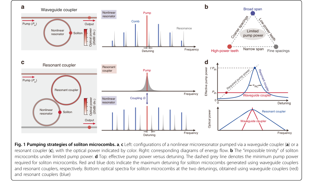 Figure 1. Pumping strategies of soliton microcombs. a, c Left: configurations of a nonlinear microresonator pumped via a waveguide coupler (a) or a resonant coupler (c), with the optical power indicated by color. Right: corresponding diagrams of energy flow. b The “impossible trinity” of soliton microcombs under limited pump power. d Top: effective pump power versus detuning. The dashed grey line denotes the minimum pump power required for soliton microcombs. Red and blue dots indicate the maximum detuning for soliton microcombs generated using waveguide couplers and resonant couplers, respectively. Bottom: optical spectra for soliton microcombs at the two detunings, obtained using waveguide couplers (red) and resonant couplers (blue)
问题定义与约束
核心问题表述与困境
本文解决的核心挑战是生成适合实际芯片级部署的高能效超宽带孤子微梳的固有困难。
输入/当前状态:
当前状态涉及在高质量(高 Q)非线性微腔(NR)中由连续波激光器泵浦生成的传统孤子微梳。这些系统依赖于克尔非线性和反常色散之间的精妙平衡来产生相干的脉冲序列。这些梳的关键性能指标是其光谱跨度(带宽)、单个梳齿的功率和重复频率(梳齿之间的间距)。在传统的波导耦合架构中,稳定的孤子形成需要输入泵浦功率($P_{in}$)超过某个阈值($P_{th}$),并且需要额外的功率来实现红失谐泵浦。
期望终点/目标状态:
最终目标是在微波重复频率下实现倍频程跨度(极宽带宽)的孤子微梳,同时显著降低泵浦消耗。这将克服“长期的泵浦功率瓶颈”,阻碍了微梳的小型化和广泛应用。这种高能效、紧凑的设备对于便携式光钟、大规模并行数据链路和现场可部署光谱仪等应用至关重要。
缺失环节与数学鸿沟:
确切的缺失环节是一种机制,能够有效地将泵浦功率输送并增强到非线性微腔,从而规避对所需梳特性产生不利标度的高功率要求。本文通过“不可能的三角”和传统微梳的控制方程来强调这一点:
$$ P_c \Delta f_{3dB}^2 / f_r < 3.1 \times \eta_{NR} P_{in} $$
在此,$P_c$ 是中心梳齿功率,$\Delta f_{3dB}$ 是 3 dB 带宽(光谱跨度),$f_r$ 是重复频率,$\eta_{NR}$ 是 NR 的负载因子。该方程揭示了一个关键的数学鸿沟:实现更宽的带宽($\Delta f_{3dB}$)或更低的重复频率($f_r$)需要显著更高的泵浦功率($P_{in}$),并且带宽的标度尤其严苛。这种二次标度使得在没有不切实际的泵浦功率的情况下实现微波重复频率的倍频程梳变得极其困难。本文旨在通过引入谐振耦合架构来弥合这一鸿沟,该架构有效地增强了输送到 NR 的泵浦功率。
困境(痛苦的权衡):
作者们称之为“不可能的三角”(图 1b)的核心困境是,在有限的泵浦功率下,同时优化三个关键性能指标——宽光谱跨度、高功率梳齿和精细梳距——极其困难。
改进一个方面通常会损害另一个方面或需要泵浦功率的指数级增加。例如,在传统系统中实现更宽的光谱跨度或更精细的梳距(较低的重复频率)需要不成比例的更多泵浦功率,使得“由于高功率要求而无法实现光子集成”的微波重复频率的倍频程梳。这种权衡使先前的研究人员陷入困境,因为任何试图突破带宽或重复频率界限的尝试都会迅速遇到高昂的功耗壁垒。
约束与失效模式
生成高能效、超宽带孤子微梳的问题由于几个严苛的现实约束而变得异常困难:
-
极端泵浦功率要求: 最显著的约束是传统微梳实现宽光谱跨度和低重复频率所需的极高光泵浦功率。如二次标度律(方程 1)所示,增加带宽或降低重复频率需要指数级更多的功率。例如,本文推断,对于波导耦合器件(图 2h),在 125 mW 和 290 mW 的泵浦功率下匹配谐振耦合器的性能将分别需要超过 1.5 W 和 2 W。
这是芯片级集成的主要障碍。
2. 有限的片上激光功率: 实际的片上激光器,对于小型化至关重要,通常提供有限的光功率。这种基本的硬件内存限制使得满足传统微梳的高泵浦功率要求具有挑战性,从而阻碍了它们集成到便携式设备中。
3. 复杂的色散管理: 孤子形成依赖于克尔非线性和反常群速度色散(GVD)之间的精确平衡。实现超宽带、倍频程跨度的梳需要仔细设计微腔的 GVD。高阶色散和拉曼自频移等非线性效应会限制可实现的最大梳跨度,并且必须经过精心平衡,这增加了显著的设计复杂性。
4. 模式相互作用与不稳定性:
* 避免的模式交叉: 在某些失谐下,非线性谐振器(NR)和谐振耦合器(RC)的模式之间的相互作用可能导致梳光谱出现“光谱杂散”和不规则性(图 2d)。虽然更大的失谐可以缓解这种情况,但它会引入其他问题。
* 调制不稳定性: 将失谐推得太远以拓宽梳可能会在谐振耦合器中引起调制不稳定性,进而破坏孤子本身的稳定性。这为最大可访问失谐设定了实际限制,从而也限制了最大梳跨度。
5. 制造精度与公差: 实现谐振耦合架构需要对 RC 和 NR 的物理参数进行极其精确的控制。这包括它们的固有和耦合品质因子,以及它们之间的耦合率。在 Si3N4 制造过程中,实现所需的广义临界耦合条件并最小化通过总线波导的直接泵浦传输需要严格的制造公差。
6. 寄生效应与功率泄漏:
* 不期望的参量振荡: 谐振耦合器本身可能遭受不期望的参量振荡,必须将其抑制(例如,通过工程化其耗散率)。
* 寄生模式耦合: 未泵浦共振之间的意外耦合可能导致梳功率从 NR 泄漏到 RC,然后通过直通端口泄漏出去,从而降低整体转换效率。
7. 即插即用操作挑战: 对于使用片上激光器的实际“即插即用”操作,自注入锁定(后向散射光重新进入激光器)等现象会扰乱激光器调谐。虽然可以利用这一点,但它需要精确调整反馈相位,通常通过压电台等外部机制,这增加了系统的复杂性并降低了其鲁棒性。
Figure 1. Pumping strategies of soliton microcombs. a, c Left: configurations of a nonlinear microresonator pumped via a waveguide coupler (a) or a resonant coupler (c), with the optical power indicated by color. Right: corresponding diagrams of energy flow. b The “impossible trinity” of soliton microcombs under limited pump power. d Top: effective pump power versus detuning. The dashed grey line denotes the minimum pump power required for soliton microcombs. Red and blue dots indicate the maximum detuning for soliton microcombs generated using waveguide couplers and resonant couplers, respectively. Bottom: optical spectra for soliton microcombs at the two detunings, obtained using waveguide couplers (red) and resonant couplers (blue)
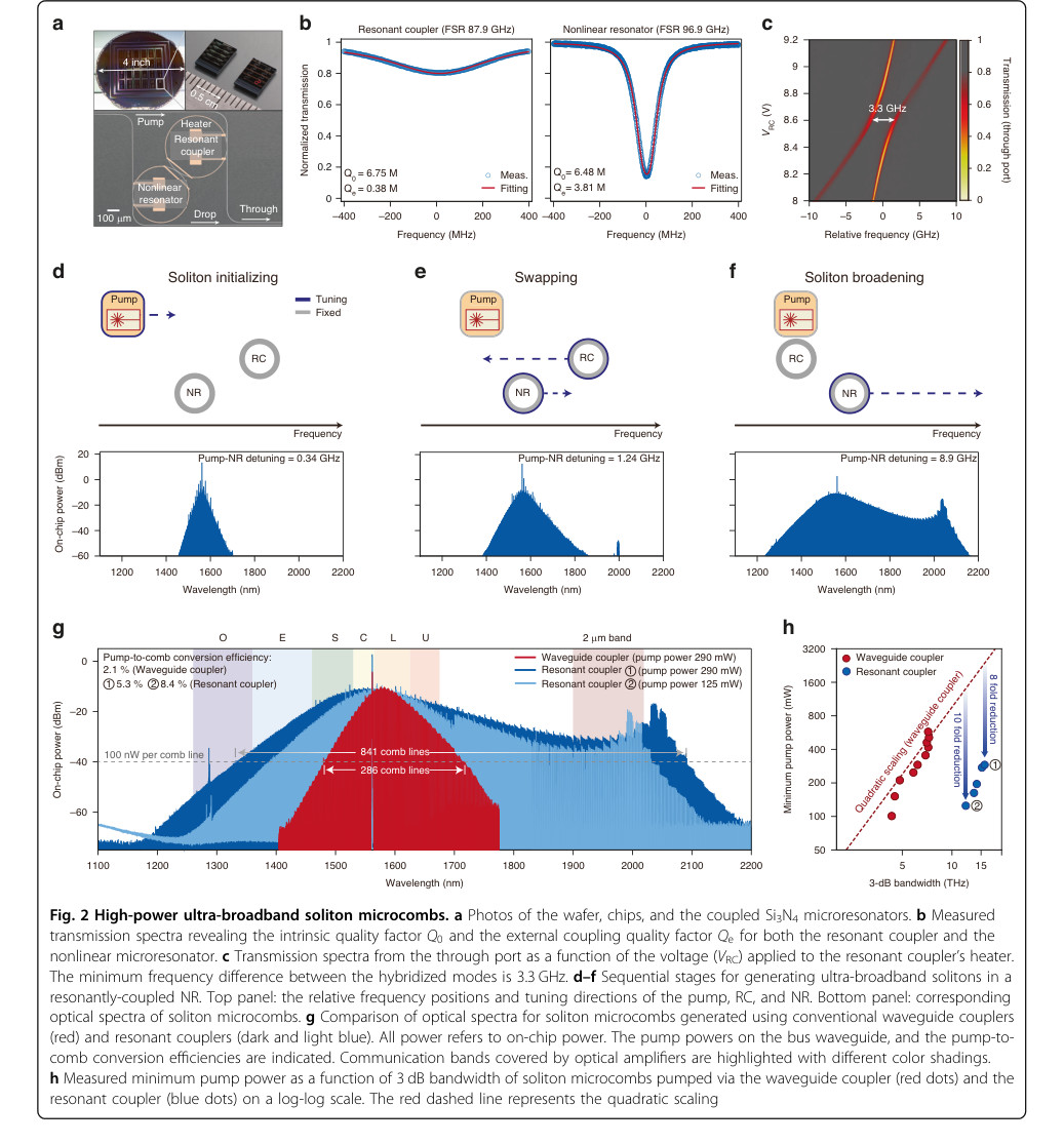 Figure 2. High-power ultra-broadband soliton microcombs. a Photos of the wafer, chips, and the coupled Si3N4 microresonators. b Measured transmission spectra revealing the intrinsic quality factor Q0 and the external coupling quality factor Qe for both the resonant coupler and the nonlinear microresonator. c Transmission spectra from the through port as a function of the voltage (VRC) applied to the resonant coupler’s heater. The minimum frequency difference between the hybridized modes is 3.3 GHz. d–f Sequential stages for generating ultra-broadband solitons in a resonantly-coupled NR. Top panel: the relative frequency positions and tuning directions of the pump, RC, and NR. Bottom panel: corresponding optical spectra of soliton microcombs. g Comparison of optical spectra for soliton microcombs generated using conventional waveguide couplers (red) and resonant couplers (dark and light blue). All power refers to on-chip power. The pump powers on the bus waveguide, and the pump-to- comb conversion efficiencies are indicated. Communication bands covered by optical amplifiers are highlighted with different color shadings. h Measured minimum pump power as a function of 3 dB bandwidth of soliton microcombs pumped via the waveguide coupler (red dots) and the resonant coupler (blue dots) on a log-log scale. The red dashed line represents the quadratic scaling
为什么选择这种方法
选择的必然性
采用谐振耦合微腔(RC)架构不仅仅是渐进式改进,更是克服孤子微梳技术关键瓶颈的根本必要性。作者们明确指出,在依赖传统波导耦合设计的情况下,“由于高功率要求,实现用于直接光-微波链路的微波重复频率的倍频程梳被认为无法实现光子集成”。这一声明标志着认识到传统最先进(SOTA)方法不足的精确时刻。
传统方法的根本限制被作者们称为“孤子微梳的‘不可能的三角’”(图 1b)。
这个概念强调,在有限的泵浦功率下,不可能同时优化梳的光谱跨度、输出功率和重复频率。控制方程 $P_c \Delta f_{3dB}^2 / f_r < 3.1 \times \eta_{NR} P_{in}$(方程 9)清楚地说明了二次标度律,使得与简单地提高梳齿功率相比,增加带宽或降低重复频率的难度呈指数级增长。缺乏高效泵浦输送机制的传统方法受到其高功耗特性的根本限制,使得倍频程梳、低重复频率和芯片级集成的宏伟目标无法实现。RC 架构作为能够从根本上改变这种功率动态的唯一可行解决方案出现了。
比较优势
谐振耦合方法提供了定性和结构上的优势,使其在性能上远远优于以前的黄金标准,主要是通过解决泵浦功率瓶颈。在结构上,该方法在总线波导和非线性谐振器(NR)之间插入了一个辅助微腔(RC)。这个看似简单的附加组件提供了输送到 NR 的泵浦功率的“谐振增强”,由增强因子 $\Gamma = 4G^2 / (K_{RC} K_{NR})$(方程 2)量化。
这种谐振增强不仅仅是微小的提升;它是一项变革。它允许系统访问显著更大的失谐(图 1d),
这反过来又“极大地增加了孤子跨度”,因为它的标度与 $\sqrt{\delta\omega}$ 成正比。与传统的波导耦合设计相比,本文展示了“高功率梳的光谱跨度增加了三倍,并且(ii)倍频程操作的重复频率降低了十倍”。更引人注目的是,RC 架构在给定带宽下实现了“高达 10 倍的泵浦功率增强”(图 2h)。
当比较用于倍频程梳生成的品质因数 $P_{in} \times f_r^2$ 时,RC 架构实现了约 $10^5 \text{ mW} \cdot \text{GHz}^2$ 的值,这比传统波导耦合配置中报告的最佳结果低了两个数量级(图 3f)。
这代表了功率效率上的深刻的定性飞跃,使得以前被认为不可能的性能得以实现。
虽然本文没有在典型的机器学习算法的上下文中讨论内存复杂性或高维噪声处理,但它确实表征了生成的梳的相位噪声(图 3e)。结果显示相位噪声与自由运行集成孤子微梳的最低报告值相当,表明谐振耦合没有引入有害的噪声特性并保持了高相干性,这对于光钟等应用至关重要。主要优势在于其打破功率-带宽-重复频率权衡的能力。
与约束的对齐
所选择的谐振耦合方法与问题的严格约束完美对齐,形成了“严苛要求与解决方案独特属性”的真正“联姻”。
-
小型化与芯片级部署: 整个架构,包括 RC 和 NR,都制造在 Si3N4 芯片上(图 2a),
直接满足了对紧凑、集成解决方案的需求。
2. 倍频程带宽: 泵浦功率的谐振增强允许显著更大的失谐,这直接转化为“极大地增加了孤子跨度”(图 1d)。这使得能够生成倍频程微梳,如从 1007 到 2130 nm(图 3b)和 1098 到 2250 nm(图 3d)的跨度所示。
-
微波重复频率: 通过克服功率瓶颈,RC 架构促进了在微波范围内生成重复频率为 100 GHz 和 25 GHz(图 3b、d、e)的梳,
这些是电子可检测的。
4. 低泵浦功率/功率效率: 这是对齐最显著的地方。RC 独特地增强泵浦输送的特性直接解决了“长期的泵浦功率瓶颈”。该方法以显著降低的泵浦功率实现了倍频程梳,在相似带宽下泵浦功率降低了 10 倍,在 $P_{in} \times f_r^2$ 指标上提高了两个数量级(图 3f)。这种对主要约束的直接缓解是“联姻”的本质。
5. 可靠的即插即用孤子生成: 本文展示了“混合集成即插即用孤子微梳”(图 4)。通过优化自注入锁定泵浦方案中的反馈相位,单孤子态被证明“每次激光器电流调谐到预定设定点时都能确定性地形成”,确保了鲁棒且实用的操作。
替代方案的拒绝
本文隐含且明确地拒绝了传统的波导耦合微腔设计,认为它们不足以实现既定目标。主要原因是“不可能的三角”(图 1b),
它从根本上限制了这些传统方法的性能。
作者们强调,“由于高功率要求,实现用于直接光-微波链路的微波重复频率的倍频程梳在光子集成方面是不可行的”。这是基于根本物理限制的直接拒绝——在没有高效泵浦输送机制的情况下,生成宽跨度、低重复频率梳的高功耗特性。
实验基准测试进一步巩固了这一拒绝。图 2h 直接比较了具有相同几何形状和 Q 因子的 RC 耦合器件与波导耦合 NR。
即使在 600 mW 的高泵浦功率下,传统器件的 3 dB 带宽也仅限于 7.2 THz。相比之下,RC 器件在显著降低的泵浦功率(125 mW 和 290 mW)下实现了 15.8 THz 的带宽。推断波导耦合器件的二次标度表明,“分别需要超过 1.5 W 和 2 W 的泵浦功率才能匹配 RC 在 125 mW 和 290 mW 时的性能”。这种巨大的功率差异凸显了为什么传统方法无法满足低功耗、倍频程梳的要求。
虽然已经提出了其他放松“不可能的三角”约束的策略(例如,在光纤或电光谐振器中),但本文侧重于展示谐振耦合器作为片上连续波泵浦孤子微梳最有效和实用的解决方案,这意味着这些其他方法要么缺乏同等性能,要么不适合特定的集成平台和目标。本文不讨论 GAN 或扩散等替代方案,因为它们是与光频梳生成完全无关的范式。
Figure 1. Pumping strategies of soliton microcombs. a, c Left: configurations of a nonlinear microresonator pumped via a waveguide coupler (a) or a resonant coupler (c), with the optical power indicated by color. Right: corresponding diagrams of energy flow. b The “impossible trinity” of soliton microcombs under limited pump power. d Top: effective pump power versus detuning. The dashed grey line denotes the minimum pump power required for soliton microcombs. Red and blue dots indicate the maximum detuning for soliton microcombs generated using waveguide couplers and resonant couplers, respectively. Bottom: optical spectra for soliton microcombs at the two detunings, obtained using waveguide couplers (red) and resonant couplers (blue)
Figure 1. Pumping strategies of soliton microcombs. a, c Left: configurations of a nonlinear microresonator pumped via a waveguide coupler (a) or a resonant coupler (c), with the optical power indicated by color. Right: corresponding diagrams of energy flow. b The “impossible trinity” of soliton microcombs under limited pump power. d Top: effective pump power versus detuning. The dashed grey line denotes the minimum pump power required for soliton microcombs. Red and blue dots indicate the maximum detuning for soliton microcombs generated using waveguide couplers and resonant couplers, respectively. Bottom: optical spectra for soliton microcombs at the two detunings, obtained using waveguide couplers (red) and resonant couplers (blue)
Figure 2. High-power ultra-broadband soliton microcombs. a Photos of the wafer, chips, and the coupled Si3N4 microresonators. b Measured transmission spectra revealing the intrinsic quality factor Q0 and the external coupling quality factor Qe for both the resonant coupler and the nonlinear microresonator. c Transmission spectra from the through port as a function of the voltage (VRC) applied to the resonant coupler’s heater. The minimum frequency difference between the hybridized modes is 3.3 GHz. d–f Sequential stages for generating ultra-broadband solitons in a resonantly-coupled NR. Top panel: the relative frequency positions and tuning directions of the pump, RC, and NR. Bottom panel: corresponding optical spectra of soliton microcombs. g Comparison of optical spectra for soliton microcombs generated using conventional waveguide couplers (red) and resonant couplers (dark and light blue). All power refers to on-chip power. The pump powers on the bus waveguide, and the pump-to- comb conversion efficiencies are indicated. Communication bands covered by optical amplifiers are highlighted with different color shadings. h Measured minimum pump power as a function of 3 dB bandwidth of soliton microcombs pumped via the waveguide coupler (red dots) and the resonant coupler (blue dots) on a log-log scale. The red dashed line represents the quadratic scaling
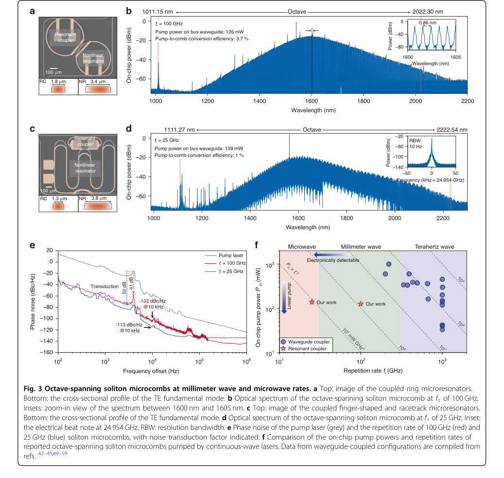 Figure 3. Octave-spanning soliton microcombs at millimeter wave and microwave rates. a Top: image of the coupled ring microresonators. Bottom: the cross-sectional profile of the TE fundamental mode. b Optical spectrum of the octave-spanning soliton microcomb at f r of 100 GHz. Insets: zoom-in view of the spectrum between 1600 nm and 1605 nm. c Top: image of the coupled finger-shaped and racetrack microresonators. Bottom: the cross-sectional profile of the TE fundamental mode. d Optical spectrum of the octave-spanning soliton microcomb at f r of 25 GHz. Inset: the electrical beat note at 24.954 GHz. RBW: resolution bandwidth. e Phase noise of the pump laser (grey) and the repetition rate of 100 GHz (red) and 25 GHz (blue) soliton microcombs, with noise transduction factor indicated. f Comparison of the on-chip pump powers and repetition rates of reported octave-spanning soliton microcombs pumped by continuous-wave lasers. Data from waveguide-coupled configurations are compiled from refs. 42–45,49–59
Figure 2. High-power ultra-broadband soliton microcombs. a Photos of the wafer, chips, and the coupled Si3N4 microresonators. b Measured transmission spectra revealing the intrinsic quality factor Q0 and the external coupling quality factor Qe for both the resonant coupler and the nonlinear microresonator. c Transmission spectra from the through port as a function of the voltage (VRC) applied to the resonant coupler’s heater. The minimum frequency difference between the hybridized modes is 3.3 GHz. d–f Sequential stages for generating ultra-broadband solitons in a resonantly-coupled NR. Top panel: the relative frequency positions and tuning directions of the pump, RC, and NR. Bottom panel: corresponding optical spectra of soliton microcombs. g Comparison of optical spectra for soliton microcombs generated using conventional waveguide couplers (red) and resonant couplers (dark and light blue). All power refers to on-chip power. The pump powers on the bus waveguide, and the pump-to- comb conversion efficiencies are indicated. Communication bands covered by optical amplifiers are highlighted with different color shadings. h Measured minimum pump power as a function of 3 dB bandwidth of soliton microcombs pumped via the waveguide coupler (red dots) and the resonant coupler (blue dots) on a log-log scale. The red dashed line represents the quadratic scaling
Figure 1. Pumping strategies of soliton microcombs. a, c Left: configurations of a nonlinear microresonator pumped via a waveguide coupler (a) or a resonant coupler (c), with the optical power indicated by color. Right: corresponding diagrams of energy flow. b The “impossible trinity” of soliton microcombs under limited pump power. d Top: effective pump power versus detuning. The dashed grey line denotes the minimum pump power required for soliton microcombs. Red and blue dots indicate the maximum detuning for soliton microcombs generated using waveguide couplers and resonant couplers, respectively. Bottom: optical spectra for soliton microcombs at the two detunings, obtained using waveguide couplers (red) and resonant couplers (blue)
Figure 3. Octave-spanning soliton microcombs at millimeter wave and microwave rates. a Top: image of the coupled ring microresonators. Bottom: the cross-sectional profile of the TE fundamental mode. b Optical spectrum of the octave-spanning soliton microcomb at f r of 100 GHz. Insets: zoom-in view of the spectrum between 1600 nm and 1605 nm. c Top: image of the coupled finger-shaped and racetrack microresonators. Bottom: the cross-sectional profile of the TE fundamental mode. d Optical spectrum of the octave-spanning soliton microcomb at f r of 25 GHz. Inset: the electrical beat note at 24.954 GHz. RBW: resolution bandwidth. e Phase noise of the pump laser (grey) and the repetition rate of 100 GHz (red) and 25 GHz (blue) soliton microcombs, with noise transduction factor indicated. f Comparison of the on-chip pump powers and repetition rates of reported octave-spanning soliton microcombs pumped by continuous-wave lasers. Data from waveguide-coupled configurations are compiled from refs. 42–45,49–59
Figure 3. Octave-spanning soliton microcombs at millimeter wave and microwave rates. a Top: image of the coupled ring microresonators. Bottom: the cross-sectional profile of the TE fundamental mode. b Optical spectrum of the octave-spanning soliton microcomb at f r of 100 GHz. Insets: zoom-in view of the spectrum between 1600 nm and 1605 nm. c Top: image of the coupled finger-shaped and racetrack microresonators. Bottom: the cross-sectional profile of the TE fundamental mode. d Optical spectrum of the octave-spanning soliton microcomb at f r of 25 GHz. Inset: the electrical beat note at 24.954 GHz. RBW: resolution bandwidth. e Phase noise of the pump laser (grey) and the repetition rate of 100 GHz (red) and 25 GHz (blue) soliton microcombs, with noise transduction factor indicated. f Comparison of the on-chip pump powers and repetition rates of reported octave-spanning soliton microcombs pumped by continuous-wave lasers. Data from waveguide-coupled configurations are compiled from refs. 42–45,49–59
Figure 3. Octave-spanning soliton microcombs at millimeter wave and microwave rates. a Top: image of the coupled ring microresonators. Bottom: the cross-sectional profile of the TE fundamental mode. b Optical spectrum of the octave-spanning soliton microcomb at f r of 100 GHz. Insets: zoom-in view of the spectrum between 1600 nm and 1605 nm. c Top: image of the coupled finger-shaped and racetrack microresonators. Bottom: the cross-sectional profile of the TE fundamental mode. d Optical spectrum of the octave-spanning soliton microcomb at f r of 25 GHz. Inset: the electrical beat note at 24.954 GHz. RBW: resolution bandwidth. e Phase noise of the pump laser (grey) and the repetition rate of 100 GHz (red) and 25 GHz (blue) soliton microcombs, with noise transduction factor indicated. f Comparison of the on-chip pump powers and repetition rates of reported octave-spanning soliton microcombs pumped by continuous-wave lasers. Data from waveguide-coupled configurations are compiled from refs. 42–45,49–59
Figure 1. Pumping strategies of soliton microcombs. a, c Left: configurations of a nonlinear microresonator pumped via a waveguide coupler (a) or a resonant coupler (c), with the optical power indicated by color. Right: corresponding diagrams of energy flow. b The “impossible trinity” of soliton microcombs under limited pump power. d Top: effective pump power versus detuning. The dashed grey line denotes the minimum pump power required for soliton microcombs. Red and blue dots indicate the maximum detuning for soliton microcombs generated using waveguide couplers and resonant couplers, respectively. Bottom: optical spectra for soliton microcombs at the two detunings, obtained using waveguide couplers (red) and resonant couplers (blue)
Figure 2. High-power ultra-broadband soliton microcombs. a Photos of the wafer, chips, and the coupled Si3N4 microresonators. b Measured transmission spectra revealing the intrinsic quality factor Q0 and the external coupling quality factor Qe for both the resonant coupler and the nonlinear microresonator. c Transmission spectra from the through port as a function of the voltage (VRC) applied to the resonant coupler’s heater. The minimum frequency difference between the hybridized modes is 3.3 GHz. d–f Sequential stages for generating ultra-broadband solitons in a resonantly-coupled NR. Top panel: the relative frequency positions and tuning directions of the pump, RC, and NR. Bottom panel: corresponding optical spectra of soliton microcombs. g Comparison of optical spectra for soliton microcombs generated using conventional waveguide couplers (red) and resonant couplers (dark and light blue). All power refers to on-chip power. The pump powers on the bus waveguide, and the pump-to- comb conversion efficiencies are indicated. Communication bands covered by optical amplifiers are highlighted with different color shadings. h Measured minimum pump power as a function of 3 dB bandwidth of soliton microcombs pumped via the waveguide coupler (red dots) and the resonant coupler (blue dots) on a log-log scale. The red dashed line represents the quadratic scaling
Figure 3. Octave-spanning soliton microcombs at millimeter wave and microwave rates. a Top: image of the coupled ring microresonators. Bottom: the cross-sectional profile of the TE fundamental mode. b Optical spectrum of the octave-spanning soliton microcomb at f r of 100 GHz. Insets: zoom-in view of the spectrum between 1600 nm and 1605 nm. c Top: image of the coupled finger-shaped and racetrack microresonators. Bottom: the cross-sectional profile of the TE fundamental mode. d Optical spectrum of the octave-spanning soliton microcomb at f r of 25 GHz. Inset: the electrical beat note at 24.954 GHz. RBW: resolution bandwidth. e Phase noise of the pump laser (grey) and the repetition rate of 100 GHz (red) and 25 GHz (blue) soliton microcombs, with noise transduction factor indicated. f Comparison of the on-chip pump powers and repetition rates of reported octave-spanning soliton microcombs pumped by continuous-wave lasers. Data from waveguide-coupled configurations are compiled from refs. 42–45,49–59
Figure 2. High-power ultra-broadband soliton microcombs. a Photos of the wafer, chips, and the coupled Si3N4 microresonators. b Measured transmission spectra revealing the intrinsic quality factor Q0 and the external coupling quality factor Qe for both the resonant coupler and the nonlinear microresonator. c Transmission spectra from the through port as a function of the voltage (VRC) applied to the resonant coupler’s heater. The minimum frequency difference between the hybridized modes is 3.3 GHz. d–f Sequential stages for generating ultra-broadband solitons in a resonantly-coupled NR. Top panel: the relative frequency positions and tuning directions of the pump, RC, and NR. Bottom panel: corresponding optical spectra of soliton microcombs. g Comparison of optical spectra for soliton microcombs generated using conventional waveguide couplers (red) and resonant couplers (dark and light blue). All power refers to on-chip power. The pump powers on the bus waveguide, and the pump-to- comb conversion efficiencies are indicated. Communication bands covered by optical amplifiers are highlighted with different color shadings. h Measured minimum pump power as a function of 3 dB bandwidth of soliton microcombs pumped via the waveguide coupler (red dots) and the resonant coupler (blue dots) on a log-log scale. The red dashed line represents the quadratic scaling
Figure 1. Pumping strategies of soliton microcombs. a, c Left: configurations of a nonlinear microresonator pumped via a waveguide coupler (a) or a resonant coupler (c), with the optical power indicated by color. Right: corresponding diagrams of energy flow. b The “impossible trinity” of soliton microcombs under limited pump power. d Top: effective pump power versus detuning. The dashed grey line denotes the minimum pump power required for soliton microcombs. Red and blue dots indicate the maximum detuning for soliton microcombs generated using waveguide couplers and resonant couplers, respectively. Bottom: optical spectra for soliton microcombs at the two detunings, obtained using waveguide couplers (red) and resonant couplers (blue)
Figure 3. Octave-spanning soliton microcombs at millimeter wave and microwave rates. a Top: image of the coupled ring microresonators. Bottom: the cross-sectional profile of the TE fundamental mode. b Optical spectrum of the octave-spanning soliton microcomb at f r of 100 GHz. Insets: zoom-in view of the spectrum between 1600 nm and 1605 nm. c Top: image of the coupled finger-shaped and racetrack microresonators. Bottom: the cross-sectional profile of the TE fundamental mode. d Optical spectrum of the octave-spanning soliton microcomb at f r of 25 GHz. Inset: the electrical beat note at 24.954 GHz. RBW: resolution bandwidth. e Phase noise of the pump laser (grey) and the repetition rate of 100 GHz (red) and 25 GHz (blue) soliton microcombs, with noise transduction factor indicated. f Comparison of the on-chip pump powers and repetition rates of reported octave-spanning soliton microcombs pumped by continuous-wave lasers. Data from waveguide-coupled configurations are compiled from refs. 42–45,49–59
Figure 3. Octave-spanning soliton microcombs at millimeter wave and microwave rates. a Top: image of the coupled ring microresonators. Bottom: the cross-sectional profile of the TE fundamental mode. b Optical spectrum of the octave-spanning soliton microcomb at f r of 100 GHz. Insets: zoom-in view of the spectrum between 1600 nm and 1605 nm. c Top: image of the coupled finger-shaped and racetrack microresonators. Bottom: the cross-sectional profile of the TE fundamental mode. d Optical spectrum of the octave-spanning soliton microcomb at f r of 25 GHz. Inset: the electrical beat note at 24.954 GHz. RBW: resolution bandwidth. e Phase noise of the pump laser (grey) and the repetition rate of 100 GHz (red) and 25 GHz (blue) soliton microcombs, with noise transduction factor indicated. f Comparison of the on-chip pump powers and repetition rates of reported octave-spanning soliton microcombs pumped by continuous-wave lasers. Data from waveguide-coupled configurations are compiled from refs. 42–45,49–59
Figure 3. Octave-spanning soliton microcombs at millimeter wave and microwave rates. a Top: image of the coupled ring microresonators. Bottom: the cross-sectional profile of the TE fundamental mode. b Optical spectrum of the octave-spanning soliton microcomb at f r of 100 GHz. Insets: zoom-in view of the spectrum between 1600 nm and 1605 nm. c Top: image of the coupled finger-shaped and racetrack microresonators. Bottom: the cross-sectional profile of the TE fundamental mode. d Optical spectrum of the octave-spanning soliton microcomb at f r of 25 GHz. Inset: the electrical beat note at 24.954 GHz. RBW: resolution bandwidth. e Phase noise of the pump laser (grey) and the repetition rate of 100 GHz (red) and 25 GHz (blue) soliton microcombs, with noise transduction factor indicated. f Comparison of the on-chip pump powers and repetition rates of reported octave-spanning soliton microcombs pumped by continuous-wave lasers. Data from waveguide-coupled configurations are compiled from refs. 42–45,49–59
Figure 1. Pumping strategies of soliton microcombs. a, c Left: configurations of a nonlinear microresonator pumped via a waveguide coupler (a) or a resonant coupler (c), with the optical power indicated by color. Right: corresponding diagrams of energy flow. b The “impossible trinity” of soliton microcombs under limited pump power. d Top: effective pump power versus detuning. The dashed grey line denotes the minimum pump power required for soliton microcombs. Red and blue dots indicate the maximum detuning for soliton microcombs generated using waveguide couplers and resonant couplers, respectively. Bottom: optical spectra for soliton microcombs at the two detunings, obtained using waveguide couplers (red) and resonant couplers (blue)
Figure 2. High-power ultra-broadband soliton microcombs. a Photos of the wafer, chips, and the coupled Si3N4 microresonators. b Measured transmission spectra revealing the intrinsic quality factor Q0 and the external coupling quality factor Qe for both the resonant coupler and the nonlinear microresonator. c Transmission spectra from the through port as a function of the voltage (VRC) applied to the resonant coupler’s heater. The minimum frequency difference between the hybridized modes is 3.3 GHz. d–f Sequential stages for generating ultra-broadband solitons in a resonantly-coupled NR. Top panel: the relative frequency positions and tuning directions of the pump, RC, and NR. Bottom panel: corresponding optical spectra of soliton microcombs. g Comparison of optical spectra for soliton microcombs generated using conventional waveguide couplers (red) and resonant couplers (dark and light blue). All power refers to on-chip power. The pump powers on the bus waveguide, and the pump-to- comb conversion efficiencies are indicated. Communication bands covered by optical amplifiers are highlighted with different color shadings. h Measured minimum pump power as a function of 3 dB bandwidth of soliton microcombs pumped via the waveguide coupler (red dots) and the resonant coupler (blue dots) on a log-log scale. The red dashed line represents the quadratic scaling
数学与逻辑机制
主方程
描述非线性微腔(NR)内孤子形成和演化的基本动力学由 Lugiato-Lefever 方程(LLE)描述。这个偏微分方程捕捉了光增益、损耗、色散和非线性之间的相互作用,这些是微梳生成的基本要素。本文底层物理学驱动孤子微梳的绝对核心方程是:
$$ \frac{\partial A}{\partial T} = -\frac{\kappa_{NR}}{2} A - i\delta\omega A + i\frac{D_2}{2}\frac{\partial^2 A}{\partial\phi^2} + ig|A|^2A + \sqrt{\frac{\kappa_{e,NR}P_{in}}{\hbar\omega_0}} $$
按项解剖
让我们剖析这个主方程的每个组成部分,以理解其数学定义、物理作用以及作者选择的算子。
-
$\frac{\partial A}{\partial T}$:
- 数学定义: 这是复场幅度 $A$ 关于慢时间 $T$ 的偏导数。
- 物理/逻辑作用: 该项代表微腔内光场的时域演化。它决定了场的幅度和相位如何随时间变化,驱动整个系统的动力学趋向稳态或孤子解。偏导数的使用表明场也具有空间依赖性(沿着环的周长)。
- 为何是偏导数: 场 $A$ 是时间 $T$ 和角坐标 $\phi$ 的函数。需要偏导数来描述其演化,同时考虑其空间轮廓。
-
$A$:
- 数学定义: 在微腔内循环的光场缓慢变化的复幅度。它被归一化,使得 $|A|^2$ 对应于腔内光子数。
- 物理/逻辑作用: 该变量是描述光场本身的核心量。其幅度平方给出给定腔内点上的瞬时光功率或光子数。
-
$T$:
- 数学定义: “慢时间”或实验室时间。
- 物理/逻辑作用: 这代表了光场包络演变的宏观时间尺度。它不同于快得多的光振荡周期。
-
$\phi$:
- 数学定义: 在与循环光脉冲一起移动的参考系中的角坐标。
- 物理/逻辑作用: 这个空间坐标描述了微腔圆周上的位置。通过使用移动的参考系,方程可以有效地描述光脉冲(孤子)在环内传播时的形状和传播。
-
$-\frac{\kappa_{NR}}{2} A$:
- 数学定义: 一个线性衰减项,与场幅度 $A$ 成正比。$\kappa_{NR}$ 是非线性谐振器的总衰减率。
- 物理/逻辑作用: 该项考虑了微腔内的所有光损耗。这包括固有损耗(由于材料吸收和散射)以及耦合损耗(光从谐振器逸出到波导)。它充当阻尼力,不断减小腔内场。
- 为何是减法: 它代表损耗,因此它减小了场幅度。
- $\kappa_{NR}$:总衰减率,定义为 $\kappa_{NR} = \kappa_{0,NR} + \kappa_{e,NR}$,其中 $\kappa_{0,NR}$ 是固有(内部)衰减率,$\kappa_{e,NR}$ 是耦合到波导的外部耦合率。
-
$-i\delta\omega A$:
- 数学定义: 一个失谐项,与 $A$ 成正比并乘以虚数单位 $i$。$\delta\omega$ 是泵浦-NR 失谐。
- 物理/逻辑作用: 该项代表泵浦激光器与微腔光学共振之间的频率失配。正的 $\delta\omega$ 意味着泵浦频率高于共振频率(蓝失谐),而负的 $\delta\omega$ 意味着泵浦频率低于共振频率(红失谐)。该项在腔内场中引起相位偏移,对于稳定孤子形成至关重要,后者通常需要红失谐。
- 为何是虚数单位 $i$: 它表明该项主要引起相位偏移而不是场幅度的变化。
-
$i\frac{D_2}{2}\frac{\partial^2 A}{\partial\phi^2}$:
- 数学定义: 二阶色散项,涉及 $A$ 关于 $\phi$ 的二阶偏导数。$D_2$ 是二阶群速度色散(GVD)。
- 物理/逻辑作用: 该项描述了光脉冲的不同频率分量在谐振器内以不同速度传播。如果 $D_2 < 0$(反常色散),则高频分量传播速度较慢,这对于通过平衡克尔非线性形成亮孤子至关重要。该项导致光脉冲要么扩展要么压缩。
- 为何是虚数单位 $i$: 色散主要影响频率分量之间的相位关系,导致脉冲重塑。
- 为何是二阶导数: 它是描述群速度频率依赖性的最低阶项,这对于脉冲传播至关重要。
-
$ig|A|^2A$:
- 数学定义: 克尔非线性项,与 $|A|^2A$ 成正比并乘以 $i$。$g$ 是非线性系数。
- 物理/逻辑作用: 该项代表自相位调制(SPM)效应。材料的折射率随光的强度($|A|^2$)而变化,导致强度依赖的相位偏移。这种效应可以平衡反常色散以形成孤子。
- 为何是虚数单位 $i$: 克尔非线性主要引起场相位偏移,而不是幅度变化。
- $g$:非线性系数,定义为 $g = \frac{\hbar\omega_0 c n_2}{n_{eff}^2 V_{eff}}$,其中 $\hbar\omega_0$ 是光子能量,$c$ 是光速,$n_2$ 是非线性折射率,$n_{eff}$ 是有效折射率,$V_{eff}$ 是有效模式体积。
-
$\sqrt{\frac{\kappa_{e,NR}P_{in}}{\hbar\omega_0}}$:
- 数学定义: 相干泵浦项,代表谐振器的外部驱动。
- 物理/逻辑作用: 该项从外部泵浦激光器连续地将光功率注入微腔。它是系统的能量来源,抵消损耗并提供四波混频和孤子形成所需的功率。
- 为何是平方根: 场幅度 $A$ 与光功率的平方根成正比。
- $\kappa_{e,NR}$:从总线波导到非线性谐振器的耦合率。
- $P_{in}$:输入泵浦功率。对于谐振耦合器(RC)架构,此 $P_{in}$ 有效地增强了 $\Gamma = \frac{4G^2}{\kappa_{RC}\kappa_{NR}}$ 的因子(来自方程 2),这意味着输送到 NR 的实际功率是 $\Gamma P_{in}$。
- $\hbar\omega_0$:泵浦频率下单个光子的能量。
步骤流程
让我们追踪一个抽象的光“数据点”(一束光子)与这个数学引擎的交互过程,特别强调谐振耦合器的作用。
- 外部泵浦注入: 连续波激光器以特定频率 $\omega_0$ 和功率 $P_{in}$ 发射光。这是进入系统的初始“数据点”。
- 谐振耦合器(RC)增强: 如果采用了谐振耦合器架构,该泵浦光首先进入辅助谐振耦合器。RC 精确调谐以与泵浦频率发生谐振,从而在光功率到达主非线性谐振器(NR)之前在 RC 内引起显著的光功率累积。这有效地放大了输送到 NR 的泵浦功率。增强因子 $\Gamma$(来自方程 2)量化了这种提升,意味着输送到 NR 的有效泵浦功率为 $\Gamma P_{in}$。在传统的波导耦合系统中,此步骤被跳过,并且 $P_{in}$ 直接耦合到 NR。
- 能量输送到非线性谐振器: (可能增强的)泵浦功率随后耦合到非线性微腔。这种连续的能量注入由 LLE 中的 $\sqrt{\frac{\kappa_{e,NR}P_{in}}{\hbar\omega_0}}$ 项表示,作为腔内场 $A$ 的恒定驱动力。
- 循环与损耗: 一旦进入 NR,光场 $A$ 开始循环。在传播过程中,其部分能量由于材料的固有吸收、散射和耦合出谐振器而持续损失。这种衰减由 $-\frac{\kappa_{NR}}{2} A$ 项建模,该项的作用是减小场。
- 失谐引起的相位演化: 泵浦激光器的频率被故意设置比 NR 的自然频率偏离 $\delta\omega$。这种失谐由 $-i\delta\omega A$ 项表示,在循环场中引起连续的相位偏移。为了实现稳定的孤子形成,通常需要特定量的“红失谐”(其中泵浦频率低于共振频率)。
- 色散引起的脉冲展宽/压缩: 随着光场在环内传播,由于材料的群速度色散($D_2$),其不同频率分量以略微不同的速度传播。$i\frac{D_2}{2}\frac{\partial^2 A}{\partial\phi^2}$ 项描述了这种色散如何重塑脉冲。对于亮孤子,反常色散($D_2 < 0$)导致脉冲压缩,抵消了否则会发生的展宽。
- 克尔非线性引起的自相位调制: 循环光本身的高强度会改变微腔材料的折射率(克尔效应)。这种强度依赖的折射率导致与光强度成正比的相位偏移,由 $ig|A|^2A$ 项描述。这种“自相位调制”(SPM)在光脉冲的峰值处比在脉冲的侧翼处更强。
- 动态平衡与孤子形成: 系统持续演化,$\frac{\partial A}{\partial T}$ 项反映了所有这些过程的净效应。当泵浦功率、失谐、色散和非线性精确平衡时,色散展宽被克尔非线性的自聚焦效应精确补偿。这种精妙的平衡允许形成稳定、自持的光脉冲——孤子——它们在不改变形状的情况下循环。这些孤子在时域中表现为脉冲序列,在频域中表现为频率梳。
- 输出与测量: 循环孤子场的一部分被连续地从谐振器耦合出来($\kappa_{e,NR}$ 的一部分),并可以作为微梳输出被检测,为各种应用做好准备。
优化动力学
该机制主要通过 LLE 项的动态相互作用和谐振耦合器的战略使用来学习、更新和收敛。
- 孤子形成作为收敛过程: 稳定孤子微梳的生成本质上是一个收敛过程。当泵浦激光器的频率扫描进入微腔的共振(通常从蓝失谐到红失谐)时,系统会经历一系列转变。最初,存在连续波光。随着泵浦功率的增加和失谐变得有利,启动了四波混频(FWM)(当 $P_{in}$ 超过阈值 $P_{th}$ 时,方程 4)。这导致了边带的生成,边带可以演变成复杂、混沌的状态,然后是调制连续波,最后,在泵浦功率、失谐和色散的正确条件下,系统收敛到稳定的单孤子或多孤子状态。LLE 描述了向稳定脉冲解的动态演化,其中 $\frac{\partial A}{\partial T} = 0$。
-
损耗景观与参数空间: 虽然没有明确地将其表述为机器学习意义上的“损耗景观”,但稳定孤子形成的条件可以被可视化为在由泵浦功率、失谐和谐振器特性(色散、损耗、非线性)定义的多个参数空间中导航。稳定的孤子状态对应于该景观中的特定区域或“谷”,在这些区域中实现了增益、损耗、色散和非线性的平衡。“不可能的三角”(方程 9)突显了塑造该景观的固有权衡和约束,表明某些性能指标无法同时最大化。
-
失谐扫描的作用: 本文强调了泵浦激光器频率跨越微腔共振扫描的重要性。这种扫描是一个关键的“学习”或“退火”步骤。通过缓慢改变失谐,系统可以平稳地从不稳定状态过渡到稳定的孤子状态,避免混沌状态。最大可访问失谐(图 1d)
直接影响微梳可实现的光谱跨度(方程 6),使得能够访问更大的失谐成为关键的优化目标。
* 谐振耦合器(RC)作为优化策略: 本文的主要创新是引入了谐振耦合器。该机制不会改变非线性谐振器内 LLE 所描述的基本物理学,但它显著优化了 NR 的输入条件。
* 增强泵浦效率: RC 通过因子 $\Gamma$(方程 2)增强了输送到 NR 的泵浦功率。这有效地增加了 LLE 中的“增益”项,而无需更高的外部泵浦功率。这是对功率效率的直接优化,允许系统以更低的输入功率达到并维持孤子状态。
* 扩展操作范围: 随着有效泵浦功率的增强,系统可以访问显著更大的红失谐(如图 1d 所示)。由于孤子跨度与失谐的平方根成正比($\Delta f_{3dB} \propto \sqrt{\delta\omega}$),因此这种扩展的操作范围直接转化为更宽的微梳。RC 有效地允许系统“探索”并收敛到更理想、更宽跨度的参数空间区域。
* 迭代状态更新(自注入锁定): 为了实现即插即用孤子生成,本文描述了使用自注入锁定。在这里,从微腔后向散射的光重新进入泵浦激光器腔。通过仔细调整反馈相位(例如,通过压电台),激光器的线宽变窄,并且系统被偏向稳定的孤子微梳生成。这构成了一个迭代反馈回路,其中激光器和谐振器系统动态调整自身以可靠地收敛到孤子状态。通过方波调制的激光器电流,导致每次电流切换时可靠地形成单孤子,这表明了收敛到所需工作点的鲁棒性和可重复性。
Figure 1. Pumping strategies of soliton microcombs. a, c Left: configurations of a nonlinear microresonator pumped via a waveguide coupler (a) or a resonant coupler (c), with the optical power indicated by color. Right: corresponding diagrams of energy flow. b The “impossible trinity” of soliton microcombs under limited pump power. d Top: effective pump power versus detuning. The dashed grey line denotes the minimum pump power required for soliton microcombs. Red and blue dots indicate the maximum detuning for soliton microcombs generated using waveguide couplers and resonant couplers, respectively. Bottom: optical spectra for soliton microcombs at the two detunings, obtained using waveguide couplers (red) and resonant couplers (blue)
Figure 1. Pumping strategies of soliton microcombs. a, c Left: configurations of a nonlinear microresonator pumped via a waveguide coupler (a) or a resonant coupler (c), with the optical power indicated by color. Right: corresponding diagrams of energy flow. b The “impossible trinity” of soliton microcombs under limited pump power. d Top: effective pump power versus detuning. The dashed grey line denotes the minimum pump power required for soliton microcombs. Red and blue dots indicate the maximum detuning for soliton microcombs generated using waveguide couplers and resonant couplers, respectively. Bottom: optical spectra for soliton microcombs at the two detunings, obtained using waveguide couplers (red) and resonant couplers (blue)
Figure 1. Pumping strategies of soliton microcombs. a, c Left: configurations of a nonlinear microresonator pumped via a waveguide coupler (a) or a resonant coupler (c), with the optical power indicated by color. Right: corresponding diagrams of energy flow. b The “impossible trinity” of soliton microcombs under limited pump power. d Top: effective pump power versus detuning. The dashed grey line denotes the minimum pump power required for soliton microcombs. Red and blue dots indicate the maximum detuning for soliton microcombs generated using waveguide couplers and resonant couplers, respectively. Bottom: optical spectra for soliton microcombs at the two detunings, obtained using waveguide couplers (red) and resonant couplers (blue)
结果、局限性与结论
实验设计与基线
为了严格验证其主张,研究人员设计了一系列实验,将他们新颖的谐振耦合器(RC)架构与传统的波导耦合设计进行了比较。核心思想是在总线波导和非线性微腔(NR)之间插入一个辅助微腔(RC),如图 1c 所示。该装置旨在谐振地增强输送到 NR 的泵浦功率,这是数学上提出的克服限制传统系统中梳跨度、功率和间距的“不可能的三角”约束(方程 1)的机制。
实验装置使用了 786 nm 厚的 Si3N4 微腔,采用减法工艺制造。使用了五个不同的器件,每个器件都针对特定的验证方面进行了定制:
- 器件 1: 一个传统的波导耦合 NR(1.8 µm 波导宽度)作为直接比较带宽和泵浦功率效率的主要基线(图 2h)。
其固有品质因子($Q_o$)为 $7.29 \times 10^6$,外部耦合品质因子($Q_e$)为 $3.83 \times 10^6$。
- 器件 2: 一个 RC 耦合 NR(RC 宽度 1.5 µm,NR 宽度 1.8 µm)用于展示高功率、超宽带孤子微梳(图 2g)。该器件的 RC $Q_o \approx 6.75 \times 10^6$ 和 $Q_e \approx 0.38 \times 10^6$,NR 的 $Q_o \approx 6.48 \times 10^6$ 和 $Q_e \approx 3.81 \times 10^6$。
-
器件 3: 一个 RC 耦合 NR(RC 宽度 1.8 µm,NR 宽度 3.4 µm)设计用于在 100 GHz 重复频率下实现倍频程孤子微梳(图 3a)。
-
器件 4: 另一个 RC 耦合 NR(RC 宽度 1.3 µm,NR 宽度 3.8 µm)专注于在较低的 25 GHz 重复频率下实现倍频程孤子微梳(图 3c)。
- 器件 5: 一个 RC 耦合 NR(RC 宽度 1 µm,NR 宽度 2.5 µm)用于展示混合集成的即插即用孤子微梳,其中片上分布式反馈(DFB)激光器直接驱动系统(图 4a)。
实验涉及小心地将泵浦激光器调谐到 RC 共振,然后将其扫描到 NR 共振以启动单孤子。通过观察生成的梳的光谱来监测此过程。为了量化相干性,使用多频延迟自外差干涉仪测量 100 GHz 梳的相位噪声,并使用商用相位噪声分析仪测量 25 GHz 梳的相位噪声。还对泵浦激光器的相位噪声进行了表征以进行比较。“受害者”在此研究中本质上是传统的波导耦合微腔,它们代表了引入谐振耦合之前的最先进技术。
证据证明了什么
实验证据明确证明,谐振耦合架构显著增强了孤子微梳的性能,特别是在光谱跨度、泵浦功率效率以及倍频程操作的重复频率降低方面。核心数学主张,即谐振耦合为输送到 NR 的泵浦功率提供了显著的增强因子 $\Gamma = \frac{4G^2}{\kappa_{RC}\kappa_{NR}}$(方程 2),得到了结果的有力支持。
以下是无可辩驳的证据:
1. 增强的带宽和梳线: 在相同的 290 mW(片上)泵浦功率下,对 RC 耦合器件(器件 2)和传统波导耦合 NR(器件 1)的直接比较(图 2h)显示出显著的改进。RC 耦合器件实现了 15.8 THz 的 3 dB 带宽和 841 条梳线,而传统器件仅实现了 6.2 THz 的带宽和 286 条梳线。这代表了带宽增加了一倍多,梳线数量增加了近三倍,直接证明了 RC 架构的卓越性能。
2. 显著降低泵浦功率: 根据二次泵浦-跨度标度(如方程 1 和图 2h 所述),
研究人员估计,传统波导耦合器件需要超过 1.5 W 至 2 W 的泵浦功率才能分别匹配 RC 耦合器件在 125 mW 和 290 mW 时的性能。这强调了谐振耦合提供的最高十倍的泵浦功率增强,这是对该架构效率的关键验证。
-
微波速率下的倍频程梳: 使用器件 3 和器件 4 的实验成功地在微波重复频率下生成了倍频程孤子微梳。器件 3 使用 126 mW 的泵浦功率在 100 GHz 重复频率下产生了从 1007 nm 到 2130 nm 的倍频程光谱(图 3b)。
器件 4 在 25 GHz 重复频率下使用 139 mW 的泵浦功率产生了从 1098 nm 到 2250 nm 的倍频程光谱(图 3d)。
这在以前被认为由于高功率要求而难以实现光子集成。
4. 卓越的品质因数: 本文引入了一个品质因数 $P_{in} \times f_r^2$,用于比较不同平台在倍频程梳生成与重复频率之间的片上泵浦功率要求(图 3f)。RC 架构实现了约 $10^5 \text{ mW} \cdot \text{GHz}^2$ 的值,这比传统波导耦合配置中报告的最佳结果低了两个数量级。这种定量比较有力地证明了效率优势。
5. 高相干性: 100 GHz 和 25 GHz 梳的相位噪声测量(图 3e)显示出优异的相干性,分别在 10 kHz 偏移处记录了 -102 dBc/Hz 和 -113 dBc/Hz。这些值与自由运行集成孤子微梳的最低报告值相当,表明生成的梳的质量很高。
6. 即插即用操作: 使用片上 DFB 激光器的混合集成设置(器件 5)展示了可靠的、确定性的单孤子生成。通过优化反馈相位,每次激光器电流调谐到预定设定点时,单孤子微梳都会稳定形成(图 4b),展示了系统的实际可行性和易用性。
局限性与未来方向
尽管谐振耦合架构标志着向前迈出了重要一步,但本文也坦诚地讨论了几项局限性,并提出了令人兴奋的未来发展方向。
一个直接的局限性是,进一步增加对于拓宽梳跨度至关重要的失谐,可能导致 RC 中的调制不稳定性,从而破坏孤子的稳定性。这一效应将可实现的最大失谐从理论预测值降低了。一个潜在的解决方案是进一步降低 RC 的品质因子($Q$),这将允许更大的失谐而不会出现不稳定性。另一个挑战来自于色散波和避免的模式交叉,特别是在 1100-1300 nm 范围内,这可能会限制可实现的最大梳跨度。平衡这些效应是实现更宽梳的关键。
本文还强调了在未使用光隔离器时自注入锁定的现象。尽管研究人员利用了这一效应来缩窄激光器的线宽并使系统偏向孤子生成,但这意味着需要通过压电台等装置进行精确的反馈相位调整才能实现稳定的孤子形成。这增加了一层复杂性,可以通过集成隔离器或更鲁棒的自锁定机制来简化。
展望未来,研究人员提出了几个关键的改进和发展领域:
- RC 和 NR 设计优化: 当前的微腔设计可以进行改进。抑制 RC 中的参量振荡,也许可以通过缩小其波导以降低固有 $Q$ 或增加与总线波导的耦合来实现。另一个关键领域是减轻非泵浦共振之间的寄生模式耦合,这可能导致梳功率泄漏。这可以通过工程化 RC 和 NR 之间的耦合,使其仅在泵浦共振附近显著来实现。最重要的是,需要精确控制 RC 和 NR 的参数,以最小化直接泵浦传输并实现所需的广义临界耦合条件。
- 优化非线性谐振器(NR): 随着泵浦功率瓶颈在很大程度上得到解决,未来的工作可以集中于设计具有更大色散的 NR。这可能导致具有更多高功率梳齿和改善的信噪比的微梳,使其更适合高级电信格式,并可能无需外部光放大。
- 鲁棒的自参考: 实现鲁棒的 f-2f 自参考,这对于光频合成和原子钟至关重要,需要精确控制色散波的生成。这是一个复杂的挑战,涉及微腔色散曲线的精细调整。
- 光谱整形: 就像输入泵浦输送得到增强一样,输出光谱本身也可以使用波长选择性耦合器进行整形。这将允许根据特定应用需求定制梳的光谱轮廓,提供更大的灵活性和实用性。
- 特定应用增强: 所展示的能力为众多机会打开了大门。例如,100 GHz 微梳非常适合高容量波分复用光通信,可能支持高达 64 Tb/s 的聚合数据速率而无需额外的光谱展平。生成小于 25 fs 的脉冲的能力可以彻底改变低占空比飞秒脉冲序列和任意光波形。进一步的研究可以侧重于针对光频分频、天文光谱仪和便携式光钟等特定应用的优化。
这些讨论点为推进孤子微梳技术提供了清晰的路线图,从基本演示转向高度优化的、面向应用的设备。这些发现为集成光子学的未来研究奠定了坚实的基础,强调了架构创新在克服固有物理限制方面的重要性。
Figure 2. High-power ultra-broadband soliton microcombs. a Photos of the wafer, chips, and the coupled Si3N4 microresonators. b Measured transmission spectra revealing the intrinsic quality factor Q0 and the external coupling quality factor Qe for both the resonant coupler and the nonlinear microresonator. c Transmission spectra from the through port as a function of the voltage (VRC) applied to the resonant coupler’s heater. The minimum frequency difference between the hybridized modes is 3.3 GHz. d–f Sequential stages for generating ultra-broadband solitons in a resonantly-coupled NR. Top panel: the relative frequency positions and tuning directions of the pump, RC, and NR. Bottom panel: corresponding optical spectra of soliton microcombs. g Comparison of optical spectra for soliton microcombs generated using conventional waveguide couplers (red) and resonant couplers (dark and light blue). All power refers to on-chip power. The pump powers on the bus waveguide, and the pump-to- comb conversion efficiencies are indicated. Communication bands covered by optical amplifiers are highlighted with different color shadings. h Measured minimum pump power as a function of 3 dB bandwidth of soliton microcombs pumped via the waveguide coupler (red dots) and the resonant coupler (blue dots) on a log-log scale. The red dashed line represents the quadratic scaling
Figure 3. Octave-spanning soliton microcombs at millimeter wave and microwave rates. a Top: image of the coupled ring microresonators. Bottom: the cross-sectional profile of the TE fundamental mode. b Optical spectrum of the octave-spanning soliton microcomb at f r of 100 GHz. Insets: zoom-in view of the spectrum between 1600 nm and 1605 nm. c Top: image of the coupled finger-shaped and racetrack microresonators. Bottom: the cross-sectional profile of the TE fundamental mode. d Optical spectrum of the octave-spanning soliton microcomb at f r of 25 GHz. Inset: the electrical beat note at 24.954 GHz. RBW: resolution bandwidth. e Phase noise of the pump laser (grey) and the repetition rate of 100 GHz (red) and 25 GHz (blue) soliton microcombs, with noise transduction factor indicated. f Comparison of the on-chip pump powers and repetition rates of reported octave-spanning soliton microcombs pumped by continuous-wave lasers. Data from waveguide-coupled configurations are compiled from refs. 42–45,49–59
Figure 2. High-power ultra-broadband soliton microcombs. a Photos of the wafer, chips, and the coupled Si3N4 microresonators. b Measured transmission spectra revealing the intrinsic quality factor Q0 and the external coupling quality factor Qe for both the resonant coupler and the nonlinear microresonator. c Transmission spectra from the through port as a function of the voltage (VRC) applied to the resonant coupler’s heater. The minimum frequency difference between the hybridized modes is 3.3 GHz. d–f Sequential stages for generating ultra-broadband solitons in a resonantly-coupled NR. Top panel: the relative frequency positions and tuning directions of the pump, RC, and NR. Bottom panel: corresponding optical spectra of soliton microcombs. g Comparison of optical spectra for soliton microcombs generated using conventional waveguide couplers (red) and resonant couplers (dark and light blue). All power refers to on-chip power. The pump powers on the bus waveguide, and the pump-to- comb conversion efficiencies are indicated. Communication bands covered by optical amplifiers are highlighted with different color shadings. h Measured minimum pump power as a function of 3 dB bandwidth of soliton microcombs pumped via the waveguide coupler (red dots) and the resonant coupler (blue dots) on a log-log scale. The red dashed line represents the quadratic scaling
Figure 2. High-power ultra-broadband soliton microcombs. a Photos of the wafer, chips, and the coupled Si3N4 microresonators. b Measured transmission spectra revealing the intrinsic quality factor Q0 and the external coupling quality factor Qe for both the resonant coupler and the nonlinear microresonator. c Transmission spectra from the through port as a function of the voltage (VRC) applied to the resonant coupler’s heater. The minimum frequency difference between the hybridized modes is 3.3 GHz. d–f Sequential stages for generating ultra-broadband solitons in a resonantly-coupled NR. Top panel: the relative frequency positions and tuning directions of the pump, RC, and NR. Bottom panel: corresponding optical spectra of soliton microcombs. g Comparison of optical spectra for soliton microcombs generated using conventional waveguide couplers (red) and resonant couplers (dark and light blue). All power refers to on-chip power. The pump powers on the bus waveguide, and the pump-to- comb conversion efficiencies are indicated. Communication bands covered by optical amplifiers are highlighted with different color shadings. h Measured minimum pump power as a function of 3 dB bandwidth of soliton microcombs pumped via the waveguide coupler (red dots) and the resonant coupler (blue dots) on a log-log scale. The red dashed line represents the quadratic scaling
Figure 3. Octave-spanning soliton microcombs at millimeter wave and microwave rates. a Top: image of the coupled ring microresonators. Bottom: the cross-sectional profile of the TE fundamental mode. b Optical spectrum of the octave-spanning soliton microcomb at f r of 100 GHz. Insets: zoom-in view of the spectrum between 1600 nm and 1605 nm. c Top: image of the coupled finger-shaped and racetrack microresonators. Bottom: the cross-sectional profile of the TE fundamental mode. d Optical spectrum of the octave-spanning soliton microcomb at f r of 25 GHz. Inset: the electrical beat note at 24.954 GHz. RBW: resolution bandwidth. e Phase noise of the pump laser (grey) and the repetition rate of 100 GHz (red) and 25 GHz (blue) soliton microcombs, with noise transduction factor indicated. f Comparison of the on-chip pump powers and repetition rates of reported octave-spanning soliton microcombs pumped by continuous-wave lasers. Data from waveguide-coupled configurations are compiled from refs. 42–45,49–59
Figure 3. Octave-spanning soliton microcombs at millimeter wave and microwave rates. a Top: image of the coupled ring microresonators. Bottom: the cross-sectional profile of the TE fundamental mode. b Optical spectrum of the octave-spanning soliton microcomb at f r of 100 GHz. Insets: zoom-in view of the spectrum between 1600 nm and 1605 nm. c Top: image of the coupled finger-shaped and racetrack microresonators. Bottom: the cross-sectional profile of the TE fundamental mode. d Optical spectrum of the octave-spanning soliton microcomb at f r of 25 GHz. Inset: the electrical beat note at 24.954 GHz. RBW: resolution bandwidth. e Phase noise of the pump laser (grey) and the repetition rate of 100 GHz (red) and 25 GHz (blue) soliton microcombs, with noise transduction factor indicated. f Comparison of the on-chip pump powers and repetition rates of reported octave-spanning soliton microcombs pumped by continuous-wave lasers. Data from waveguide-coupled configurations are compiled from refs. 42–45,49–59
Figure 3. Octave-spanning soliton microcombs at millimeter wave and microwave rates. a Top: image of the coupled ring microresonators. Bottom: the cross-sectional profile of the TE fundamental mode. b Optical spectrum of the octave-spanning soliton microcomb at f r of 100 GHz. Insets: zoom-in view of the spectrum between 1600 nm and 1605 nm. c Top: image of the coupled finger-shaped and racetrack microresonators. Bottom: the cross-sectional profile of the TE fundamental mode. d Optical spectrum of the octave-spanning soliton microcomb at f r of 25 GHz. Inset: the electrical beat note at 24.954 GHz. RBW: resolution bandwidth. e Phase noise of the pump laser (grey) and the repetition rate of 100 GHz (red) and 25 GHz (blue) soliton microcombs, with noise transduction factor indicated. f Comparison of the on-chip pump powers and repetition rates of reported octave-spanning soliton microcombs pumped by continuous-wave lasers. Data from waveguide-coupled configurations are compiled from refs. 42–45,49–59
Figure 3. Octave-spanning soliton microcombs at millimeter wave and microwave rates. a Top: image of the coupled ring microresonators. Bottom: the cross-sectional profile of the TE fundamental mode. b Optical spectrum of the octave-spanning soliton microcomb at f r of 100 GHz. Insets: zoom-in view of the spectrum between 1600 nm and 1605 nm. c Top: image of the coupled finger-shaped and racetrack microresonators. Bottom: the cross-sectional profile of the TE fundamental mode. d Optical spectrum of the octave-spanning soliton microcomb at f r of 25 GHz. Inset: the electrical beat note at 24.954 GHz. RBW: resolution bandwidth. e Phase noise of the pump laser (grey) and the repetition rate of 100 GHz (red) and 25 GHz (blue) soliton microcombs, with noise transduction factor indicated. f Comparison of the on-chip pump powers and repetition rates of reported octave-spanning soliton microcombs pumped by continuous-wave lasers. Data from waveguide-coupled configurations are compiled from refs. 42–45,49–59
与其他领域的同构性
结构骨架
一个系统利用中间谐振结构来放大和高效传输输入能量,从而使非线性过程能够在受限资源下实现显著扩展的稳定操作范围。