공진 결합 마이크로공진기에서의 저전력 초광대역 솔리톤 마이크로콤
The drive to miniaturize optical frequency combs for practical deployment has spotlighted microresonator solitons as a promising chip-scale candidate.
배경 및 학문적 계보
기원 및 학문적 계보
본 논문에서 다루는 문제의 정확한 기원은 첨단 광 주파수 콤을 특수 실험실 환경에서 벗어나 실질적인 실제 응용 분야로 전환하려는 지속적인 노력에서 비롯된다. 발명된 지 거의 20년이 지난 광 주파수 콤은 혁신적인 도구였지만, 광범위한 배포는 크기와 전력 소비로 인해 방해받아 왔다. 따라서 집적 광학 분야에서는 이러한 장치의 소형화에 초점을 맞춰 왔으며, 이는 솔리톤 마이크로콤을 유망한 칩 스케일 솔루션으로 주목하게 만들었다.
그러나 이전 접근 방식의 근본적인 한계, 즉 "고충점(pain point)"이 명확해졌다. 이러한 칩 스케일 솔리톤 마이크로콤은 종종 매우 많은 전력을 소비했으며, 특히 연구자들이 더 넓은 스펙트럼 범위(옥타브 스패닝 콤과 같은) 또는 더 미세한 콤 간격(많은 응용 분야에 중요함)을 목표로 할 때 더욱 그랬다. 본 논문은 직접적인 광-마이크로파 연동을 위한 마이크로파 반복율에서의 옥타브 스패닝 콤을 달성하는 것이 "높은 전력 요구 사항으로 인해 광 집적에서는 불가능하다"고 간주되었다고 명시적으로 밝힌다. 비선형 마이크로공진기와 버스 도파관이 직접 결합되는 기존 아키텍처는 4파 혼합을 시작하기 위해 입력 펌프 전력($P_{in}$)이 특정 임계값($P_{th}$)을 초과해야 하며, 안정적인 솔리톤 형성을 위해서는 더 많은 전력이 필요하다. 이는 소형, 저전력, 광대역 마이크로콤의 실현을 방해하는 상당한 "펌프 전력 병목 현상"을 초래했다. 저자들은 특히 대역폭을 늘리거나 반복율을 줄이는 것이 극도로 전력 집약적이게 만드는 이차 스케일링 법칙으로 인해 제한된 펌프 전력 하에서 콤 스팬, 전력 및 간격을 동시에 최적화할 수 없는 "불가능한 삼위일체(impossible trinity)"라고 부르는 이 병목 현상을 극복하기 위해 이 논문을 작성해야 했다.
전통적인 접근 방식의 핵심적인 한계는 저자들이 "솔리톤 마이크로콤의 불가능한 삼위일체(impossible trinity)"라고 명명한 것에 요약되어 있다 (그림 1b).
이 개념은 제한된 펌프 전력 하에서는 콤의 스펙트럼 스팬, 출력 전력 및 반복율을 동시에 최적화하는 것이 불가능하다는 것을 강조한다.
직관적인 도메인 용어
- 광 주파수 콤 (Optical Frequency Comb): 길이를 측정하는 대신 빛의 주파수를 측정하는 초정밀 자를 상상해 보라. 이 자는 완벽하게 균일하게 간격을 둔 "이빨"(머리빗과 같은)을 가지고 있으며, 이 이빨은 특정하고 매우 안정적인 주파수의 빛으로 만들어진다. 이 이빨은 다른 광원을 극도로 정확하게 측정하거나 매우 정밀한 타이밍 신호를 생성할 수 있는 참조점으로 작용한다.
- 솔리톤 마이크로콤 (Soliton Microcomb): 모양을 바꾸지 않고 바다를 건너는 외로운 바다 파도와 같은 완벽하게 안정적이고 자체 유지되는 빛의 파동을 상상해 보라. 이제 이 빛의 파동이 아주 작고 매우 효율적인 광 루프(마이크로공진기) 안에 갇혀 순환한다고 상상해 보라. 이 안정성은 빛 자체 내의 섬세한 힘의 균형에서 비롯된다. 이 안정적인 빛의 파동이 반복적으로 생성될 때 광 주파수 콤의 "이빨"을 생성한다.
- 마이크로공진기 (Microresonator): 이것은 본질적으로 빛을 위한 소형 고품질 경주로이다. 빛은 이 작은 고리나 디스크로 들어가 수많은 번 순환하며 강도를 높인다. "고품질 계수(high-Q)"는 빛이 각 랩마다 에너지를 거의 잃지 않음을 의미하며, 이는 콤 생성을 위해 필수적인 빛과 물질 간의 강한 상호 작용을 가능하게 한다.
- 옥타브 스패닝 (Octave-spanning): 음악에서 옥타브는 음표의 주파수를 두 배로 늘리는 것(예: 중간 C에서 높은 C)을 의미한다. 광 콤의 맥락에서 "옥타브 스패닝"은 콤이 커버하는 주파수 범위가 가장 높은 주파수가 가장 낮은 주파수의 최소 두 배가 될 정도로 광대하다는 것을 의미한다. 이 극도로 넓은 커버리지는 콤 자체에 대한 절대적인 내장 주파수 표준을 갖는 것과 같은 자체 참조와 같은 고급 응용 분야에 필수적이다.
- 공진 결합 (Resonant-coupling): 이것은 광 전달 시스템에 터보차저를 추가하는 것과 같다. 주요 "경주로"(비선형 마이크로공진기)에 직접 빛을 주입하는 대신, 먼저 보조 "부스터" 공진기로 보낸다. 이 부스터는 들어오는 빛과 공명하도록 특별히 조정되어 메인 공진기로 효율적으로 전달되기 전에 펌프 전력을 효과적으로 증폭하고 집중시킨다. 이는 솔리톤 마이크로콤 생성의 전체 과정을 훨씬 더 전력 효율적으로 만든다.
표기법 표
| 표기법 | 설명 | 유형 |
|---|---|---|
| $P_{in}$ | 입력 펌프 전력 | 변수 |
| $\Delta f_{3dB}$ | 광 주파수 콤의 3dB 대역폭 | 변수 |
| $P_c$ | 광 주파수 콤의 중심 이빨 전력 | 변수 |
| $f_r$ | 광 주파수 콤의 반복율 | 변수 |
| $\delta\omega$ | 펌프-비선형 공진기(NR) 디튜닝 | 변수 |
| $\kappa_{NR}$ | 비선형 공진기(NR)의 총 소산율 | 매개변수 |
| $\kappa_{RC}$ | 공진 커플러(RC)의 총 소산율 | 매개변수 |
| $G$ | 공진 커플러(RC)와 비선형 공진기(NR) 간의 결합율 | 매개변수 |
| $\Gamma$ | 공진 결합으로 인한 유효 펌프 전력 증강 계수 | 매개변수 |
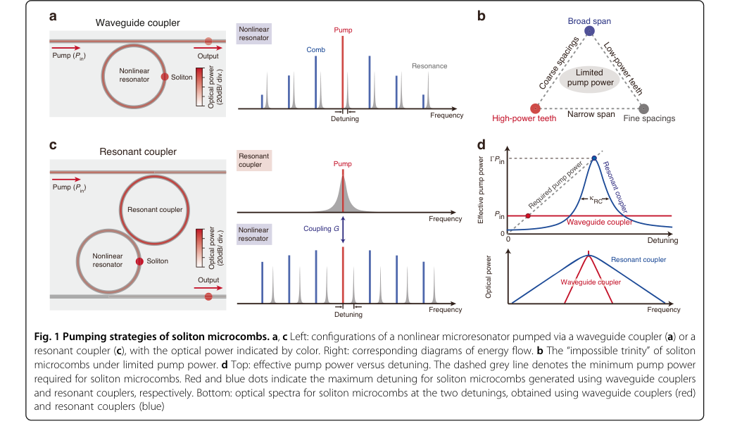 Figure 1. Pumping strategies of soliton microcombs. a, c Left: configurations of a nonlinear microresonator pumped via a waveguide coupler (a) or a resonant coupler (c), with the optical power indicated by color. Right: corresponding diagrams of energy flow. b The “impossible trinity” of soliton microcombs under limited pump power. d Top: effective pump power versus detuning. The dashed grey line denotes the minimum pump power required for soliton microcombs. Red and blue dots indicate the maximum detuning for soliton microcombs generated using waveguide couplers and resonant couplers, respectively. Bottom: optical spectra for soliton microcombs at the two detunings, obtained using waveguide couplers (red) and resonant couplers (blue)
문제 정의 및 제약 조건
핵심 문제 공식화 및 딜레마
본 논문에서 다루는 핵심 과제는 실용적인 칩 스케일 배포에 적합한 저전력 초광대역 솔리톤 마이크로콤 생성의 내재된 어려움이다.
입력/현재 상태:
현재 상태는 연속파 레이저로 펌핑되는 고품질(고-Q) 비선형 마이크로공진기(NR)에서 생성되는 기존 솔리톤 마이크로콤을 포함한다. 이러한 시스템은 Kerr 비선형성과 이상 분산 간의 섬세한 균형에 의존하여 위상 결합된 펄스 열을 생성한다. 이러한 콤의 주요 성능 지표는 스펙트럼 스팬(대역폭), 개별 콤 이빨의 전력 및 반복율(이빨 간 간격)이다. 기존 도파관 결합 아키텍처에서 안정적인 솔리톤 형성을 위해서는 입력 펌프 전력($P_{in}$)이 특정 임계값($P_{th}$)을 초과해야 하며, 적색 디튜닝된 펌프를 위해서는 추가 전력이 필요하다.
원하는 최종점/목표 상태:
궁극적인 목표는 마이크로파 반복율에서 옥타브 스패닝(극도로 넓은 대역폭) 솔리톤 마이크로콤을 상당히 감소된 펌프 소비로 달성하는 것이다. 이는 마이크로콤의 소형화 및 광범위한 채택을 방해해 온 "오래된 펌프 전력 병목 현상"을 극복할 것이다. 이러한 저전력, 소형 장치는 휴대용 광 시계, 대규모 병렬 데이터 링크 및 현장 배치형 분광기와 같은 응용 분야에 필수적이다.
누락된 연결 및 수학적 격차:
정확한 누락된 연결은 비선형 마이크로공진기에 펌프 전력을 효율적으로 전달하고 증강하여, 원하는 콤 특성에 불리하게 스케일링되는 높은 전력 요구 사항을 우회하는 메커니즘이다. 본 논문은 "불가능한 삼위일체"와 기존 마이크로콤에 대한 지배적인 제약 조건을 통해 이를 강조한다.
$$ P_c \Delta f_{3dB}^2 / f_r < 3.1 \times \eta_{NR} P_{in} $$
여기서 $P_c$는 중심 이빨 전력, $\Delta f_{3dB}$는 3dB 대역폭(스펙트럼 스팬), $f_r$는 반복율, $\eta_{NR}$는 NR의 로딩 계수이다. 이 방정식은 중요한 수학적 격차를 드러낸다: 더 넓은 대역폭($\Delta f_{3dB}$) 또는 더 낮은 반복율($f_r$)을 달성하려면 상당한 양의 펌프 전력($P_{in}$)이 필요하며, 특히 대역폭에 대한 가혹한 이차 스케일링이 있다. 이 이차 스케일링은 비실용적인 양의 펌프 전력 없이는 마이크로파 반복율에서 옥타브 스패닝 콤을 달성하는 것을 극도로 어렵게 만든다. 본 논문은 NR에 전달되는 펌프 전력을 효과적으로 증강하는 공진 결합 아키텍처를 도입하여 이 격차를 해소하는 것을 목표로 한다.
딜레마 (고통스러운 절충):
저자들이 "불가능한 삼위일체"라고 명명한 핵심 딜레마(그림 1b)는 세 가지 주요 성능 지표—넓은 스펙트럼 스팬, 고출력 콤 이빨 및 미세한 콤 간격—를 동시에 최적화하는 것이 제한된 펌프 전력 하에서는 극도로 어렵다는 것이다.
한 가지 측면을 개선하면 일반적으로 다른 측면이 저하되거나 펌프 전력의 기하급수적인 증가가 필요하다. 예를 들어, 기존 시스템에서 더 넓은 스펙트럼 스팬 또는 더 미세한 콤 간격을 달성하려면 불균형적으로 더 많은 펌프 전력이 필요하며, 이는 마이크로파 반복율에서의 옥타브 스패닝 콤을 "높은 전력 요구 사항으로 인해 광 집적에서는 불가능하다"고 만든다. 이 절충은 이전 연구자들을 가두었으며, 대역폭 또는 반복율의 경계를 밀어붙이려는 모든 시도는 금지된 전력 소비의 벽에 빠르게 부딪힌다.
제약 조건 및 실패 모드
저전력, 초광대역 솔리톤 마이크로콤 생성 문제는 몇 가지 가혹하고 현실적인 제약 조건으로 인해 엄청나게 어렵다.
- 극심한 펌프 전력 요구 사항: 가장 중요한 제약 조건은 넓은 스펙트럼 스팬과 낮은 반복율을 달성하기 위해 기존 마이크로콤에 필요한 높은 광 펌프 전력이다. 이차 스케일링 법칙(식 1)에서 알 수 있듯이, 대역폭을 늘리거나 반복율을 줄이면 기하급수적으로 더 많은 전력이 필요하다. 예를 들어, 본 논문은 125mW 및 290mW 펌프 전력에서 공진 커플러의 성능을 일치시키기 위해 도파관 결합 장치의 경우 각각 1.5W 및 2W 이상이 필요할 것이라고 추정한다(그림 2h).
이는 칩 스케일 집적의 주요 장애물이다.
2. 제한된 온칩 레이저 전력: 소형화를 위해 필수적인 실용적인 온칩 레이저는 일반적으로 제한된 광 전력을 제공한다. 이 근본적인 하드웨어 메모리 제한은 기존 마이크로콤의 높은 펌프 전력 요구 사항을 충족하기 어렵게 만들어 휴대용 장치에 통합하는 것을 방해한다.
3. 복잡한 분산 관리: 솔리톤 형성은 Kerr 비선형성과 이상 그룹 속도 분산(GVD) 간의 정밀한 균형에 의존한다. 초광대역, 옥타브 스패닝 콤을 달성하려면 마이크로공진기의 GVD를 신중하게 설계해야 한다. 고차 분산 및 라만 자체 주파수 이동과 같은 비선형 효과는 달성 가능한 최대 콤 스팬을 제한할 수 있으며 세심하게 균형을 맞춰야 하므로 설계 복잡성이 크게 증가한다.
4. 모드 상호 작용 및 불안정성:
* 회피된 모드 교차: 특정 디튜닝에서 비선형 공진기(NR)와 공진 커플러(RC)의 모드 간의 상호 작용은 "스펙트럼 스퍼"와 콤 스펙트럼의 불규칙성을 유발할 수 있다(그림 2d). 더 큰 디튜닝이 이를 완화할 수 있지만 다른 문제를 야기한다.
* 변조 불안정성: 콤을 넓히기 위해 디튜닝을 너무 많이 하면 공진 커플러에서 변조 불안정성이 유발될 수 있으며, 이는 다시 솔리톤 자체를 불안정하게 만든다. 이는 최대 접근 가능한 디튜닝, 결과적으로 최대 콤 스팬에 대한 실용적인 제한을 설정한다.
5. 제조 정밀도 및 허용 오차: 공진 결합 아키텍처를 실현하려면 RC와 NR 모두의 물리적 매개변수에 대한 극도로 정밀한 제어가 필요하다. 여기에는 고유 및 결합 품질 계수, 그리고 공진기 간 결합율이 포함된다. 원하는 일반화된 임계 결합 조건을 달성하고 버스 도파관을 통한 직접적인 펌프 전달을 최소화하려면 Si3N4 제조 공정에서 엄격한 제조 허용 오차가 필요하다.
6. 기생 효과 및 전력 누출:
* 원치 않는 매개변수 발진: 공진 커플러 자체는 원치 않는 매개변수 발진으로 고통받을 수 있으며, 이는 억제되어야 한다(예: 소산율을 설계하여).
* 기생 모드 결합: 펌핑되지 않은 공명 간의 의도하지 않은 결합은 콤 전력을 NR에서 RC로, 그리고 다시 통과 포트로 누출시켜 전체 변환 효율을 감소시킬 수 있다.
7. 턴키 작동의 어려움: 온칩 레이저를 사용한 실용적인 "턴키" 작동의 경우, 자체 주입 잠금(레이저에서 반사된 빛이 다시 레이저로 들어가는 현상)과 같은 현상이 레이저 튜닝을 방해할 수 있다. 이를 활용할 수 있지만 외부 메커니즘(예: 압전 스테이지)을 통한 정밀한 피드백 위상 조정이 필요하며, 이는 시스템의 복잡성을 증가시키고 견고성을 감소시킨다.
Figure 1. Pumping strategies of soliton microcombs. a, c Left: configurations of a nonlinear microresonator pumped via a waveguide coupler (a) or a resonant coupler (c), with the optical power indicated by color. Right: corresponding diagrams of energy flow. b The “impossible trinity” of soliton microcombs under limited pump power. d Top: effective pump power versus detuning. The dashed grey line denotes the minimum pump power required for soliton microcombs. Red and blue dots indicate the maximum detuning for soliton microcombs generated using waveguide couplers and resonant couplers, respectively. Bottom: optical spectra for soliton microcombs at the two detunings, obtained using waveguide couplers (red) and resonant couplers (blue)
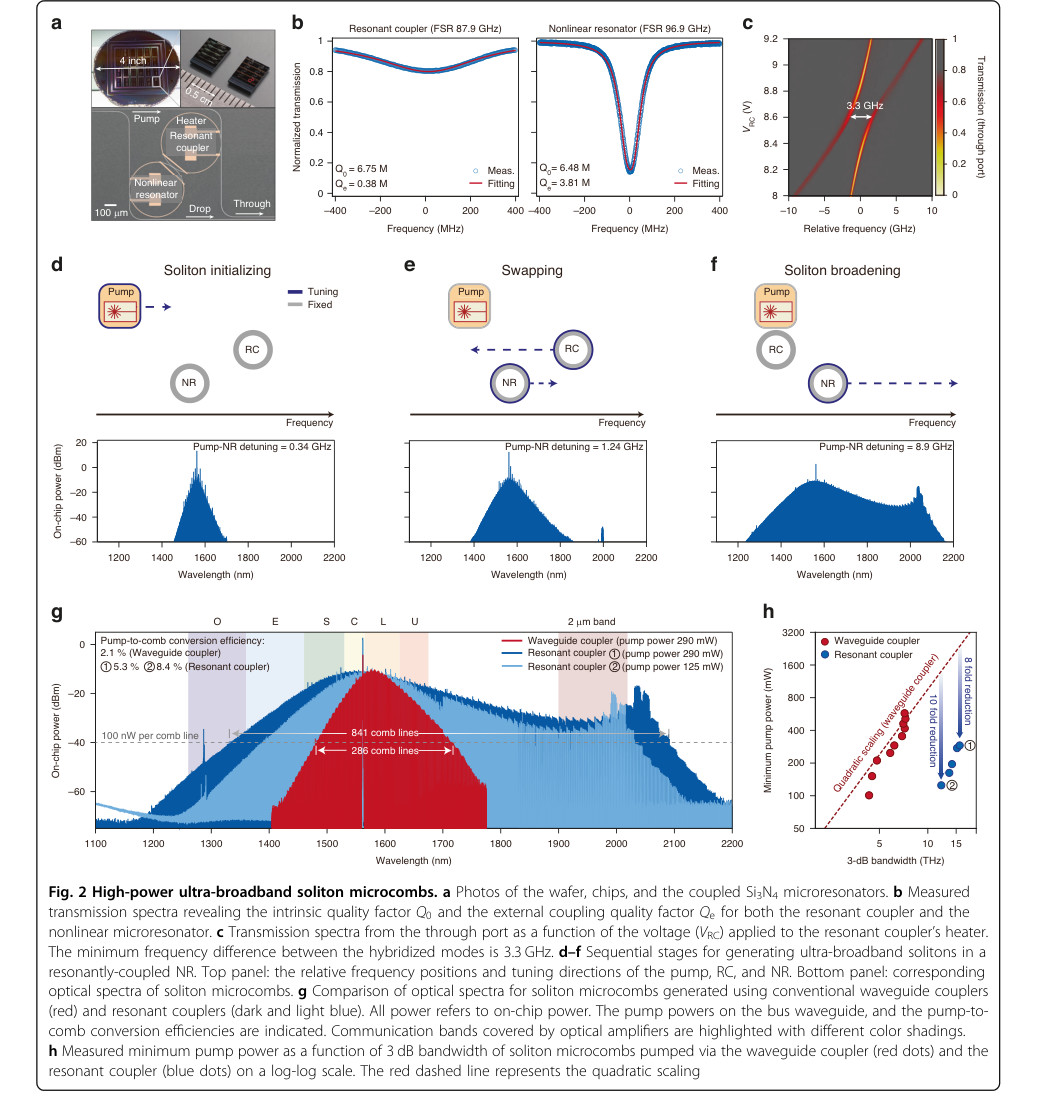 Figure 2. High-power ultra-broadband soliton microcombs. a Photos of the wafer, chips, and the coupled Si3N4 microresonators. b Measured transmission spectra revealing the intrinsic quality factor Q0 and the external coupling quality factor Qe for both the resonant coupler and the nonlinear microresonator. c Transmission spectra from the through port as a function of the voltage (VRC) applied to the resonant coupler’s heater. The minimum frequency difference between the hybridized modes is 3.3 GHz. d–f Sequential stages for generating ultra-broadband solitons in a resonantly-coupled NR. Top panel: the relative frequency positions and tuning directions of the pump, RC, and NR. Bottom panel: corresponding optical spectra of soliton microcombs. g Comparison of optical spectra for soliton microcombs generated using conventional waveguide couplers (red) and resonant couplers (dark and light blue). All power refers to on-chip power. The pump powers on the bus waveguide, and the pump-to- comb conversion efficiencies are indicated. Communication bands covered by optical amplifiers are highlighted with different color shadings. h Measured minimum pump power as a function of 3 dB bandwidth of soliton microcombs pumped via the waveguide coupler (red dots) and the resonant coupler (blue dots) on a log-log scale. The red dashed line represents the quadratic scaling
왜 이 접근 방식인가
선택의 불가피성
공진 결합 마이크로공진기(RC) 아키텍처의 채택은 솔리톤 마이크로콤 기술의 중요한 병목 현상을 극복하기 위한 근본적인 필요성이었지 단순한 점진적인 개선이 아니었다. 저자들은 "마이크로파 반복율에서의 옥타브 스패닝 콤을 직접적인 광-마이크로파 연동을 위해 높은 전력 요구 사항으로 인해 광 집적에서는 불가능하다"고 명시적으로 밝히며, 이는 전통적인 도파관 결합 설계를 사용하는 경우에 해당한다. 이 문장은 기존 최첨단(SOTA) 방법이 불충분하다는 것을 정확히 나타낸다.
전통적인 접근 방식의 핵심적인 한계는 저자들이 "솔리톤 마이크로콤의 불가능한 삼위일체(impossible trinity)"라고 명명한 것에 요약되어 있다 (그림 1b).
이 개념은 제한된 펌프 전력 하에서는 콤의 스펙트럼 스팬, 출력 전력 및 반복율을 동시에 최적화하는 것이 불가능하다는 것을 강조한다. 지배적인 방정식인 $P_c \Delta f_{3dB}^2 / f_r < 3.1 \times \eta_{NR} P_{in}$ (식 9)는 명확하게 이차 스케일링 법칙을 보여주며, 이는 단순히 이빨 전력을 증폭하는 것보다 대역폭을 늘리거나 반복율을 줄이는 것을 기하급수적으로 더 어렵게 만든다. 효율적인 펌프 전달 메커니즘이 부족한 전통적인 방법은 본질적으로 이러한 전력 집약적인 특성에 의해 제약을 받았으며, 옥타브 스패닝, 저반복율 및 칩 스케일 집적이라는 야심찬 목표를 달성할 수 없었다. RC 아키텍처는 이 전력 역학을 근본적으로 변경할 수 있는 유일하게 실행 가능한 솔루션으로 등장했다.
비교 우위
공진 결합 접근 방식은 주로 펌프 전력 병목 현상을 해결함으로써 이전의 골드 스탠다드에 비해 질적 및 구조적 우위를 제공한다. 구조적으로 이 방법은 보조 마이크로공진기(RC)를 버스 도파관과 비선형 공진기(NR) 사이에 삽입한다. 이 단순해 보이는 추가 기능은 NR에 전달되는 펌프 전력의 "공진 증강"을 제공하며, 이는 $\Gamma = 4G^2 / (K_{RC} K_{NR})$ (식 2)라는 증강 계수로 정량화된다.
이 공진 증강은 사소한 부스트가 아니라 게임 체인저이다. 이는 시스템이 훨씬 더 큰 디튜닝(그림 1d)에 접근할 수 있도록 하며,
이는 다시 $\sqrt{\delta\omega}$와 함께 스케일링되는 "솔리톤 스팬을 극적으로 증가시킨다". 본 논문은 전통적인 도파관 결합 설계에 비해 "고출력 콤의 스펙트럼 스팬 3배 증가 및 (ii) 옥타브 스패닝 작동을 위한 반복 주파수 최대 10배 감소"를 보여준다. 더욱 놀라운 것은 RC 아키텍처가 주어진 대역폭에 대해 "최대 10배의 펌프 전력 증강"(그림 2h)을 달성한다는 것이다.
옥타브 스패닝 콤 생성을 위한 $P_{in} \times f_r^2$의 성능 지표를 비교할 때, RC 아키텍처는 약 $10^5 \text{ mW} \cdot \text{GHz}^2$의 값을 달성하며, 이는 "전통적인 도파관 결합 구성에서 보고된 최고의 결과보다 두 자릿수 낮다"(그림 3f).
이는 전력 효율성에서 심오한 질적 도약을 나타내며, 이전에 불가능하다고 여겨졌던 성능을 가능하게 한다.
본 논문은 일반적인 기계 학습 알고리즘의 맥락에서 메모리 복잡성이나 고차원 노이즈 처리를 논의하지는 않지만, 생성된 콤의 위상 노이즈를 특성화한다(그림 3e). 결과는 자유 실행 통합 솔리톤 마이크로콤에 대해 보고된 가장 낮은 값과 비교할 수 있는 위상 노이즈를 보여주며, 이는 공진 결합이 유해한 노이즈 특성을 도입하지 않고 높은 결합도를 유지함을 나타내며, 이는 광 시계와 같은 응용 분야에 중요하다. 주요 우위는 전력-대역폭-반복율 절충을 깨는 능력에 있다.
제약 조건과의 정렬
선택된 공진 결합 방법은 문제의 엄격한 제약 조건과 완벽하게 일치하며, "가혹한 요구 사항과 솔루션의 고유한 특성 간의 진정한 "결합"을 형성한다.
- 소형화 및 칩 스케일 배포: 전체 아키텍처(RC 및 NR 포함)는 Si3N4 칩(그림 2a)에 제작되어,
소형 통합 솔루션에 대한 요구 사항을 직접적으로 충족한다.
2. 옥타브 스패닝 대역폭: 펌프 전력의 공진 증강은 훨씬 더 큰 디튜닝을 가능하게 하며, 이는 "극적으로 증가된 솔리톤 스팬"(그림 1d)으로 직접 이어진다.
이는 1007~2130nm(그림 3b) 및 1098~2250nm(그림 3d)의 스팬으로 옥타브 스패닝 마이크로콤 생성을 가능하게 한다.
- 마이크로파 반복율: 펌프 전력 병목 현상을 극복함으로써 RC 아키텍처는 100GHz 및 25GHz(그림 3b, d, e)와 같은 마이크로파 영역의 반복율을 가진 콤 생성을 촉진하며,
이는 전자적으로 감지 가능하다.
4. 낮은 펌프 전력 / 전력 효율성: 이것이 정렬이 가장 두드러지는 부분이다. RC의 공진 펌프 전달 증강이라는 고유한 속성은 "오래된 펌프 전력 병목 현상"을 직접적으로 해결한다. 이 방법은 유사한 대역폭에 대해 훨씬 낮은 펌프 전력으로 옥타브 스패닝 콤을 달성하며, 펌프 전력의 10배 감소와 $P_{in} \times f_r^2$ 성능 지표에서 두 자릿수 개선을 보여준다(그림 3f).
이러한 직접적인 제약 조건 완화가 "결합"의 본질이다.
5. 안정적인 턴키 솔리톤 생성: 본 논문은 "하이브리드 통합 턴키 솔리톤 마이크로콤"(그림 4)을 시연한다. 자체 주입 잠금 펌핑 방식에서 피드백 위상을 최적화함으로써 단일 솔리톤 상태는 "레이저 전류가 미리 결정된 설정점으로 조정될 때마다 결정론적으로 형성된다"고 보여주며, 견고하고 실용적인 작동을 보장한다.
대안의 거부
본 논문은 암묵적으로 그리고 명시적으로 기존 도파관 결합 마이크로공진기 설계를 목표 달성에 부적합한 것으로 거부한다. 주요 이유는 "불가능한 삼위일체"(그림 1b)에서 비롯되며,
이는 이러한 전통적인 방법의 성능을 근본적으로 제한한다.
저자들은 "마이크로파 반복율에서의 옥타브 스패닝 콤을 직접적인 광-마이크로파 연동을 위해 높은 전력 요구 사항으로 인해 광 집적에서는 불가능하다"고 강조하며, 이는 기존 설계에 해당한다. 이것은 효율적인 펌프 전달 메커니즘 없이 넓은 스팬, 낮은 반복율의 콤을 생성하는 전력 집약적인 특성이라는 근본적인 물리적 한계에 기반한 직접적인 거부이다.
실험적 벤치마킹은 이러한 거부를 더욱 공고히 한다. 그림 2h는 동일한 기하학적 구조와 Q 계수를 가진 RC 아키텍처와 도파관 결합 NR을 직접 비교한다.
기존 장치는 600mW의 높은 펌프 전력에서도 7.2 THz의 3dB 대역폭으로 제한된다. 대조적으로, RC 장치는 훨씬 낮은 펌프 전력(125mW 및 290mW)으로 15.8 THz의 대역폭을 달성한다. 도파관 결합 장치에 대한 이차 스케일링을 외삽하면 "각각 125mW 및 290mW 펌프 전력에서 RC의 성능을 일치시키려면 1.5W 및 2W 이상이 필요할 것"이라고 시사한다. 이 엄청난 전력 차이는 전통적인 방법이 저전력, 옥타브 스패닝 요구 사항을 충족하지 못하는 이유를 강조한다.
"불가능한 삼위일체" 제약 조건을 완화하기 위한 다른 전략(예: 광섬유 또는 전기광학 공진기)이 제안되었지만, 본 논문은 공진 커플러를 통합 플랫폼 및 목표에 가장 적합하고 실용적인 솔루션으로 보여주면서, 이러한 다른 접근 방식이 동일한 수준의 성능을 제공하지 못하거나 덜 적합하다고 암시하면서, 온칩, 연속파 펌핑 솔리톤 마이크로콤에 가장 효과적이고 실용적인 솔루션으로 보여주는 데 중점을 둔다. 본 논문은 GAN 또는 Diffusion과 같은 대안을 논의하지 않는데, 이는 광 주파수 콤 생성과 전혀 관련 없는 완전히 다른 패러다임이기 때문이다.
Figure 1. Pumping strategies of soliton microcombs. a, c Left: configurations of a nonlinear microresonator pumped via a waveguide coupler (a) or a resonant coupler (c), with the optical power indicated by color. Right: corresponding diagrams of energy flow. b The “impossible trinity” of soliton microcombs under limited pump power. d Top: effective pump power versus detuning. The dashed grey line denotes the minimum pump power required for soliton microcombs. Red and blue dots indicate the maximum detuning for soliton microcombs generated using waveguide couplers and resonant couplers, respectively. Bottom: optical spectra for soliton microcombs at the two detunings, obtained using waveguide couplers (red) and resonant couplers (blue)
Figure 1. Pumping strategies of soliton microcombs. a, c Left: configurations of a nonlinear microresonator pumped via a waveguide coupler (a) or a resonant coupler (c), with the optical power indicated by color. Right: corresponding diagrams of energy flow. b The “impossible trinity” of soliton microcombs under limited pump power. d Top: effective pump power versus detuning. The dashed grey line denotes the minimum pump power required for soliton microcombs. Red and blue dots indicate the maximum detuning for soliton microcombs generated using waveguide couplers and resonant couplers, respectively. Bottom: optical spectra for soliton microcombs at the two detunings, obtained using waveguide couplers (red) and resonant couplers (blue)
Figure 2. High-power ultra-broadband soliton microcombs. a Photos of the wafer, chips, and the coupled Si3N4 microresonators. b Measured transmission spectra revealing the intrinsic quality factor Q0 and the external coupling quality factor Qe for both the resonant coupler and the nonlinear microresonator. c Transmission spectra from the through port as a function of the voltage (VRC) applied to the resonant coupler’s heater. The minimum frequency difference between the hybridized modes is 3.3 GHz. d–f Sequential stages for generating ultra-broadband solitons in a resonantly-coupled NR. Top panel: the relative frequency positions and tuning directions of the pump, RC, and NR. Bottom panel: corresponding optical spectra of soliton microcombs. g Comparison of optical spectra for soliton microcombs generated using conventional waveguide couplers (red) and resonant couplers (dark and light blue). All power refers to on-chip power. The pump powers on the bus waveguide, and the pump-to- comb conversion efficiencies are indicated. Communication bands covered by optical amplifiers are highlighted with different color shadings. h Measured minimum pump power as a function of 3 dB bandwidth of soliton microcombs pumped via the waveguide coupler (red dots) and the resonant coupler (blue dots) on a log-log scale. The red dashed line represents the quadratic scaling
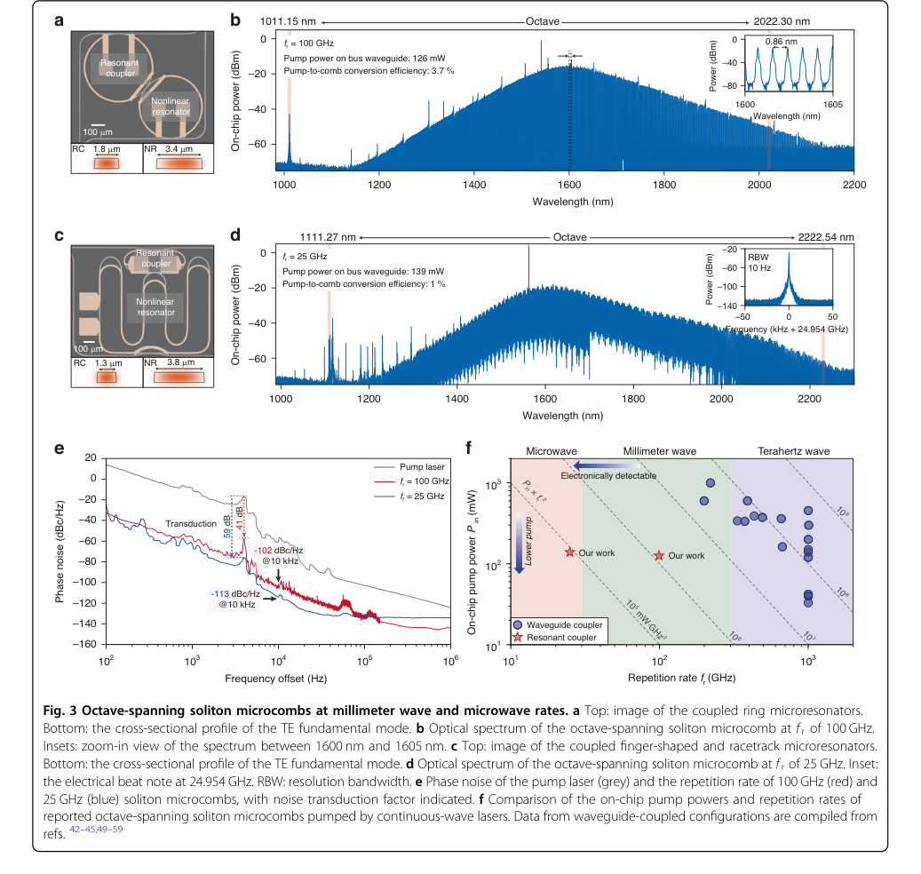 Figure 3. Octave-spanning soliton microcombs at millimeter wave and microwave rates. a Top: image of the coupled ring microresonators. Bottom: the cross-sectional profile of the TE fundamental mode. b Optical spectrum of the octave-spanning soliton microcomb at f r of 100 GHz. Insets: zoom-in view of the spectrum between 1600 nm and 1605 nm. c Top: image of the coupled finger-shaped and racetrack microresonators. Bottom: the cross-sectional profile of the TE fundamental mode. d Optical spectrum of the octave-spanning soliton microcomb at f r of 25 GHz. Inset: the electrical beat note at 24.954 GHz. RBW: resolution bandwidth. e Phase noise of the pump laser (grey) and the repetition rate of 100 GHz (red) and 25 GHz (blue) soliton microcombs, with noise transduction factor indicated. f Comparison of the on-chip pump powers and repetition rates of reported octave-spanning soliton microcombs pumped by continuous-wave lasers. Data from waveguide-coupled configurations are compiled from refs. 42–45,49–59
Figure 2. High-power ultra-broadband soliton microcombs. a Photos of the wafer, chips, and the coupled Si3N4 microresonators. b Measured transmission spectra revealing the intrinsic quality factor Q0 and the external coupling quality factor Qe for both the resonant coupler and the nonlinear microresonator. c Transmission spectra from the through port as a function of the voltage (VRC) applied to the resonant coupler’s heater. The minimum frequency difference between the hybridized modes is 3.3 GHz. d–f Sequential stages for generating ultra-broadband solitons in a resonantly-coupled NR. Top panel: the relative frequency positions and tuning directions of the pump, RC, and NR. Bottom panel: corresponding optical spectra of soliton microcombs. g Comparison of optical spectra for soliton microcombs generated using conventional waveguide couplers (red) and resonant couplers (dark and light blue). All power refers to on-chip power. The pump powers on the bus waveguide, and the pump-to- comb conversion efficiencies are indicated. Communication bands covered by optical amplifiers are highlighted with different color shadings. h Measured minimum pump power as a function of 3 dB bandwidth of soliton microcombs pumped via the waveguide coupler (red dots) and the resonant coupler (blue dots) on a log-log scale. The red dashed line represents the quadratic scaling
Figure 1. Pumping strategies of soliton microcombs. a, c Left: configurations of a nonlinear microresonator pumped via a waveguide coupler (a) or a resonant coupler (c), with the optical power indicated by color. Right: corresponding diagrams of energy flow. b The “impossible trinity” of soliton microcombs under limited pump power. d Top: effective pump power versus detuning. The dashed grey line denotes the minimum pump power required for soliton microcombs. Red and blue dots indicate the maximum detuning for soliton microcombs generated using waveguide couplers and resonant couplers, respectively. Bottom: optical spectra for soliton microcombs at the two detunings, obtained using waveguide couplers (red) and resonant couplers (blue)
Figure 3. Octave-spanning soliton microcombs at millimeter wave and microwave rates. a Top: image of the coupled ring microresonators. Bottom: the cross-sectional profile of the TE fundamental mode. b Optical spectrum of the octave-spanning soliton microcomb at f r of 100 GHz. Insets: zoom-in view of the spectrum between 1600 nm and 1605 nm. c Top: image of the coupled finger-shaped and racetrack microresonators. Bottom: the cross-sectional profile of the TE fundamental mode. d Optical spectrum of the octave-spanning soliton microcomb at f r of 25 GHz. Inset: the electrical beat note at 24.954 GHz. RBW: resolution bandwidth. e Phase noise of the pump laser (grey) and the repetition rate of 100 GHz (red) and 25 GHz (blue) soliton microcombs, with noise transduction factor indicated. f Comparison of the on-chip pump powers and repetition rates of reported octave-spanning soliton microcombs pumped by continuous-wave lasers. Data from waveguide-coupled configurations are compiled from refs. 42–45,49–59
Figure 3. Octave-spanning soliton microcombs at millimeter wave and microwave rates. a Top: image of the coupled ring microresonators. Bottom: the cross-sectional profile of the TE fundamental mode. b Optical spectrum of the octave-spanning soliton microcomb at f r of 100 GHz. Insets: zoom-in view of the spectrum between 1600 nm and 1605 nm. c Top: image of the coupled finger-shaped and racetrack microresonators. Bottom: the cross-sectional profile of the TE fundamental mode. d Optical spectrum of the octave-spanning soliton microcomb at f r of 25 GHz. Inset: the electrical beat note at 24.954 GHz. RBW: resolution bandwidth. e Phase noise of the pump laser (grey) and the repetition rate of 100 GHz (red) and 25 GHz (blue) soliton microcombs, with noise transduction factor indicated. f Comparison of the on-chip pump powers and repetition rates of reported octave-spanning soliton microcombs pumped by continuous-wave lasers. Data from waveguide-coupled configurations are compiled from refs. 42–45,49–59
Figure 3. Octave-spanning soliton microcombs at millimeter wave and microwave rates. a Top: image of the coupled ring microresonators. Bottom: the cross-sectional profile of the TE fundamental mode. b Optical spectrum of the octave-spanning soliton microcomb at f r of 100 GHz. Insets: zoom-in view of the spectrum between 1600 nm and 1605 nm. c Top: image of the coupled finger-shaped and racetrack microresonators. Bottom: the cross-sectional profile of the TE fundamental mode. d Optical spectrum of the octave-spanning soliton microcomb at f r of 25 GHz. Inset: the electrical beat note at 24.954 GHz. RBW: resolution bandwidth. e Phase noise of the pump laser (grey) and the repetition rate of 100 GHz (red) and 25 GHz (blue) soliton microcombs, with noise transduction factor indicated. f Comparison of the on-chip pump powers and repetition rates of reported octave-spanning soliton microcombs pumped by continuous-wave lasers. Data from waveguide-coupled configurations are compiled from refs. 42–45,49–59
Figure 1. Pumping strategies of soliton microcombs. a, c Left: configurations of a nonlinear microresonator pumped via a waveguide coupler (a) or a resonant coupler (c), with the optical power indicated by color. Right: corresponding diagrams of energy flow. b The “impossible trinity” of soliton microcombs under limited pump power. d Top: effective pump power versus detuning. The dashed grey line denotes the minimum pump power required for soliton microcombs. Red and blue dots indicate the maximum detuning for soliton microcombs generated using waveguide couplers and resonant couplers, respectively. Bottom: optical spectra for soliton microcombs at the two detunings, obtained using waveguide couplers (red) and resonant couplers (blue)
Figure 2. High-power ultra-broadband soliton microcombs. a Photos of the wafer, chips, and the coupled Si3N4 microresonators. b Measured transmission spectra revealing the intrinsic quality factor Q0 and the external coupling quality factor Qe for both the resonant coupler and the nonlinear microresonator. c Transmission spectra from the through port as a function of the voltage (VRC) applied to the resonant coupler’s heater. The minimum frequency difference between the hybridized modes is 3.3 GHz. d–f Sequential stages for generating ultra-broadband solitons in a resonantly-coupled NR. Top panel: the relative frequency positions and tuning directions of the pump, RC, and NR. Bottom panel: corresponding optical spectra of soliton microcombs. g Comparison of optical spectra for soliton microcombs generated using conventional waveguide couplers (red) and resonant couplers (dark and light blue). All power refers to on-chip power. The pump powers on the bus waveguide, and the pump-to- comb conversion efficiencies are indicated. Communication bands covered by optical amplifiers are highlighted with different color shadings. h Measured minimum pump power as a function of 3 dB bandwidth of soliton microcombs pumped via the waveguide coupler (red dots) and the resonant coupler (blue dots) on a log-log scale. The red dashed line represents the quadratic scaling
Figure 3. Octave-spanning soliton microcombs at millimeter wave and microwave rates. a Top: image of the coupled ring microresonators. Bottom: the cross-sectional profile of the TE fundamental mode. b Optical spectrum of the octave-spanning soliton microcomb at f r of 100 GHz. Insets: zoom-in view of the spectrum between 1600 nm and 1605 nm. c Top: image of the coupled finger-shaped and racetrack microresonators. Bottom: the cross-sectional profile of the TE fundamental mode. d Optical spectrum of the octave-spanning soliton microcomb at f r of 25 GHz. Inset: the electrical beat note at 24.954 GHz. RBW: resolution bandwidth. e Phase noise of the pump laser (grey) and the repetition rate of 100 GHz (red) and 25 GHz (blue) soliton microcombs, with noise transduction factor indicated. f Comparison of the on-chip pump powers and repetition rates of reported octave-spanning soliton microcombs pumped by continuous-wave lasers. Data from waveguide-coupled configurations are compiled from refs. 42–45,49–59
Figure 2. High-power ultra-broadband soliton microcombs. a Photos of the wafer, chips, and the coupled Si3N4 microresonators. b Measured transmission spectra revealing the intrinsic quality factor Q0 and the external coupling quality factor Qe for both the resonant coupler and the nonlinear microresonator. c Transmission spectra from the through port as a function of the voltage (VRC) applied to the resonant coupler’s heater. The minimum frequency difference between the hybridized modes is 3.3 GHz. d–f Sequential stages for generating ultra-broadband solitons in a resonantly-coupled NR. Top panel: the relative frequency positions and tuning directions of the pump, RC, and NR. Bottom panel: corresponding optical spectra of soliton microcombs. g Comparison of optical spectra for soliton microcombs generated using conventional waveguide couplers (red) and resonant couplers (dark and light blue). All power refers to on-chip power. The pump powers on the bus waveguide, and the pump-to- comb conversion efficiencies are indicated. Communication bands covered by optical amplifiers are highlighted with different color shadings. h Measured minimum pump power as a function of 3 dB bandwidth of soliton microcombs pumped via the waveguide coupler (red dots) and the resonant coupler (blue dots) on a log-log scale. The red dashed line represents the quadratic scaling
Figure 1. Pumping strategies of soliton microcombs. a, c Left: configurations of a nonlinear microresonator pumped via a waveguide coupler (a) or a resonant coupler (c), with the optical power indicated by color. Right: corresponding diagrams of energy flow. b The “impossible trinity” of soliton microcombs under limited pump power. d Top: effective pump power versus detuning. The dashed grey line denotes the minimum pump power required for soliton microcombs. Red and blue dots indicate the maximum detuning for soliton microcombs generated using waveguide couplers and resonant couplers, respectively. Bottom: optical spectra for soliton microcombs at the two detunings, obtained using waveguide couplers (red) and resonant couplers (blue)
Figure 3. Octave-spanning soliton microcombs at millimeter wave and microwave rates. a Top: image of the coupled ring microresonators. Bottom: the cross-sectional profile of the TE fundamental mode. b Optical spectrum of the octave-spanning soliton microcomb at f r of 100 GHz. Insets: zoom-in view of the spectrum between 1600 nm and 1605 nm. c Top: image of the coupled finger-shaped and racetrack microresonators. Bottom: the cross-sectional profile of the TE fundamental mode. d Optical spectrum of the octave-spanning soliton microcomb at f r of 25 GHz. Inset: the electrical beat note at 24.954 GHz. RBW: resolution bandwidth. e Phase noise of the pump laser (grey) and the repetition rate of 100 GHz (red) and 25 GHz (blue) soliton microcombs, with noise transduction factor indicated. f Comparison of the on-chip pump powers and repetition rates of reported octave-spanning soliton microcombs pumped by continuous-wave lasers. Data from waveguide-coupled configurations are compiled from refs. 42–45,49–59
Figure 3. Octave-spanning soliton microcombs at millimeter wave and microwave rates. a Top: image of the coupled ring microresonators. Bottom: the cross-sectional profile of the TE fundamental mode. b Optical spectrum of the octave-spanning soliton microcomb at f r of 100 GHz. Insets: zoom-in view of the spectrum between 1600 nm and 1605 nm. c Top: image of the coupled finger-shaped and racetrack microresonators. Bottom: the cross-sectional profile of the TE fundamental mode. d Optical spectrum of the octave-spanning soliton microcomb at f r of 25 GHz. Inset: the electrical beat note at 24.954 GHz. RBW: resolution bandwidth. e Phase noise of the pump laser (grey) and the repetition rate of 100 GHz (red) and 25 GHz (blue) soliton microcombs, with noise transduction factor indicated. f Comparison of the on-chip pump powers and repetition rates of reported octave-spanning soliton microcombs pumped by continuous-wave lasers. Data from waveguide-coupled configurations are compiled from refs. 42–45,49–59
Figure 3. Octave-spanning soliton microcombs at millimeter wave and microwave rates. a Top: image of the coupled ring microresonators. Bottom: the cross-sectional profile of the TE fundamental mode. b Optical spectrum of the octave-spanning soliton microcomb at f r of 100 GHz. Insets: zoom-in view of the spectrum between 1600 nm and 1605 nm. c Top: image of the coupled finger-shaped and racetrack microresonators. Bottom: the cross-sectional profile of the TE fundamental mode. d Optical spectrum of the octave-spanning soliton microcomb at f r of 25 GHz. Inset: the electrical beat note at 24.954 GHz. RBW: resolution bandwidth. e Phase noise of the pump laser (grey) and the repetition rate of 100 GHz (red) and 25 GHz (blue) soliton microcombs, with noise transduction factor indicated. f Comparison of the on-chip pump powers and repetition rates of reported octave-spanning soliton microcombs pumped by continuous-wave lasers. Data from waveguide-coupled configurations are compiled from refs. 42–45,49–59
Figure 1. Pumping strategies of soliton microcombs. a, c Left: configurations of a nonlinear microresonator pumped via a waveguide coupler (a) or a resonant coupler (c), with the optical power indicated by color. Right: corresponding diagrams of energy flow. b The “impossible trinity” of soliton microcombs under limited pump power. d Top: effective pump power versus detuning. The dashed grey line denotes the minimum pump power required for soliton microcombs. Red and blue dots indicate the maximum detuning for soliton microcombs generated using waveguide couplers and resonant couplers, respectively. Bottom: optical spectra for soliton microcombs at the two detunings, obtained using waveguide couplers (red) and resonant couplers (blue)
Figure 2. High-power ultra-broadband soliton microcombs. a Photos of the wafer, chips, and the coupled Si3N4 microresonators. b Measured transmission spectra revealing the intrinsic quality factor Q0 and the external coupling quality factor Qe for both the resonant coupler and the nonlinear microresonator. c Transmission spectra from the through port as a function of the voltage (VRC) applied to the resonant coupler’s heater. The minimum frequency difference between the hybridized modes is 3.3 GHz. d–f Sequential stages for generating ultra-broadband solitons in a resonantly-coupled NR. Top panel: the relative frequency positions and tuning directions of the pump, RC, and NR. Bottom panel: corresponding optical spectra of soliton microcombs. g Comparison of optical spectra for soliton microcombs generated using conventional waveguide couplers (red) and resonant couplers (dark and light blue). All power refers to on-chip power. The pump powers on the bus waveguide, and the pump-to- comb conversion efficiencies are indicated. Communication bands covered by optical amplifiers are highlighted with different color shadings. h Measured minimum pump power as a function of 3 dB bandwidth of soliton microcombs pumped via the waveguide coupler (red dots) and the resonant coupler (blue dots) on a log-log scale. The red dashed line represents the quadratic scaling
수학적 및 논리적 메커니즘
마스터 방정식
비선형 마이크로공진기(NR) 내에서 광 솔리톤의 형성 및 진화를 지배하는 근본적인 역학은 Lugiato-Lefever 방정식(LLE)으로 설명된다. 이 편미분 방정식은 마이크로콤 생성을 위해 필수적인 광 이득, 손실, 분산 및 비선형성 간의 상호 작용을 포착한다. 본 논문의 솔리톤 마이크로콤에 대한 기본 물리학을 뒷받침하는 절대적인 핵심 방정식은 다음과 같다.
$$ \frac{\partial A}{\partial T} = -\frac{\kappa_{NR}}{2} A - i\delta\omega A + i\frac{D_2}{2}\frac{\partial^2 A}{\partial\phi^2} + ig|A|^2A + \sqrt{\frac{\kappa_{e,NR}P_{in}}{\hbar\omega_0}} $$
항별 분석
이 마스터 방정식의 각 구성 요소를 분해하여 수학적 정의, 물리적 역할 및 저자가 선택한 연산자를 이해해 보자.
-
$\frac{\partial A}{\partial T}$:
- 수학적 정의: 복소 필드 진폭 $A$의 느린 시간 $T$에 대한 편미분이다.
- 물리적/논리적 역할: 이 항은 마이크로공진기 내에서 광 필드의 시간적 진화를 나타낸다. 이는 필드의 진폭과 위상이 시간에 따라 어떻게 변하는지를 결정하며, 전체 시스템의 역학을 정상 상태 또는 솔리톤 해로 이끈다. 편미분 사용은 필드가 공간적 의존성(공진기 둘레)도 가지고 있음을 의미한다.
- 왜 편미분인가: 필드 $A$는 시간 $T$와 각도 좌표 $\phi$ 모두의 함수이다. 공간 프로파일을 고려하면서 그 진화를 설명하려면 편미분이 필요하다.
-
$A$:
- 수학적 정의: 마이크로공진기 내에서 순환하는 광 필드의 느리게 변하는 복소 진폭이다. $|A|^2$가 공진기 내 광자 수에 해당하도록 정규화된다.
- 물리적/논리적 역할: 이 변수는 빛 필드 자체를 설명하는 중심 양이다. 그 크기의 제곱은 주어진 공진기 지점에서 순간적인 광 전력 또는 광자 수를 제공한다.
-
$T$:
- 수학적 정의: "느린 시간" 또는 실험실 시간이다.
- 물리적/논리적 역할: 이는 광 필드 봉투가 진화하는 거시적 시간 규모를 나타낸다. 훨씬 더 빠른 광 진동 주기와는 구별된다.
-
$\phi$:
- 수학적 정의: 순환하는 광 펄스와 함께 이동하는 기준 프레임에서의 각도 좌표이다.
- 물리적/논리적 역할: 이 공간 좌표는 마이크로공진기 둘레의 위치를 설명한다. 이동 프레임을 사용함으로써 이 방정식은 펄스(솔리톤)가 고리 주위를 이동할 때의 모양과 전파를 효과적으로 설명할 수 있다.
-
$-\frac{\kappa_{NR}}{2} A$:
- 수학적 정의: 필드 진폭 $A$에 비례하는 선형 감쇠 항이다. $\kappa_{NR}$은 비선형 공진기의 총 감쇠율이다.
- 물리적/논리적 역할: 이 항은 마이크로공진기 내의 모든 광 손실을 설명한다. 여기에는 고유 손실(물질 흡수 및 산란으로 인한)과 공진기에서 도파관으로 빛이 빠져나가는 결합 손실이 포함된다. 이는 내부 필드를 지속적으로 감소시키는 감쇠력으로 작용한다.
- 왜 빼기인가: 손실을 나타내므로 필드 진폭을 감소시킨다.
- $\kappa_{NR}$: 총 감쇠율은 $\kappa_{NR} = \kappa_{0,NR} + \kappa_{e,NR}$로 정의되며, 여기서 $\kappa_{0,NR}$은 고유(내부) 감쇠율이고 $\kappa_{e,NR}$은 도파관으로의 외부 결합율이다.
-
$-i\delta\omega A$:
- 수학적 정의: 허수 단위 $i$와 곱해진 $A$에 비례하는 디튜닝 항이다. $\delta\omega$는 펌프-NR 디튜닝이다.
- 물리적/논리적 역할: 이 항은 펌프 레이저와 마이크로공진기의 광 공명 간의 주파수 불일치를 나타낸다. 양수 $\delta\omega$는 펌프가 공명보다 높은 주파수(청색 디튜닝)에 있음을 의미하고, 음수 $\delta\omega$는 낮은 주파수(적색 디튜닝)에 있음을 의미한다. 이 항은 순환 필드에 위상 이동을 유도하며, 일반적으로 적색 디튜닝을 요구하는 안정적인 솔리톤 형성에 중요하다.
- 왜 허수 단위 $i$인가: 이는 주로 진폭 변화가 아닌 위상 이동을 유발한다는 것을 의미한다.
-
$i\frac{D_2}{2}\frac{\partial^2 A}{\partial\phi^2}$:
- 수학적 정의: $\phi$에 대한 두 번째 편미분을 포함하는 이차 분산 항이다. $D_2$는 이차 그룹 속도 분산(GVD)이다.
- 물리적/논리적 역할: 이 항은 광 펄스의 서로 다른 주파수 구성 요소가 공진기 내에서 다른 속도로 이동하는 방식을 설명한다. $D_2 < 0$ (이상 분산)이면 고주파수가 느리게 이동하며, 이는 Kerr 비선형성과 균형을 이루어 밝은 솔리톤을 형성하는 데 필수적이다. 이 항은 광 펄스를 퍼지게 하거나 압축시킨다.
- 왜 허수 단위 $i$인가: 분산은 주로 주파수 구성 요소 간의 위상 관계에 영향을 미쳐 펄스 재형성을 유발한다.
- 왜 이차 미분인가: 이는 그룹 속도의 주파수 의존성을 설명하는 가장 낮은 차수의 항이며, 펄스 전파에 중요하다.
-
$ig|A|^2A$:
- 수학적 정의: $i$와 곱해진 $|A|^2A$에 비례하는 Kerr 비선형 항이다. $g$는 비선형 계수이다.
- 물리적/논리적 역할: 이 항은 자체 위상 변조(SPM) 효과를 나타낸다. 물질의 굴절률은 빛의 강도($|A|^2$)에 따라 변하며, 강도 의존적인 위상 이동을 유발한다. 이 효과는 이상 분산을 균형 맞춰 솔리톤을 형성할 수 있다.
- 왜 허수 단위 $i$인가: Kerr 비선형성은 주로 필드의 진폭 변화가 아닌 위상 이동을 유발한다.
- $g$: 비선형 계수는 $g = \frac{\hbar\omega_0 c n_2}{n_{eff}^2 V_{eff}}$로 정의되며, 여기서 $\hbar\omega_0$는 광자 에너지, $c$는 빛의 속도, $n_2$는 비선형 굴절률, $n_{eff}$는 유효 굴절률, $V_{eff}$는 유효 모드 부피이다.
-
$\sqrt{\frac{\kappa_{e,NR}P_{in}}{\hbar\omega_0}}$:
- 수학적 정의: 공진기의 외부 구동을 나타내는 일관된 펌프 항이다.
- 물리적/논리적 역할: 이 항은 외부 펌프 레이저에서 마이크로공진기로 광 전력을 지속적으로 주입한다. 이는 시스템의 에너지원으로 작용하여 손실을 상쇄하고 4파 혼합 및 솔리톤 형성에 필요한 전력을 제공한다.
- 왜 제곱근인가: 필드 진폭 $A$는 광 전력의 제곱근에 비례한다.
- $\kappa_{e,NR}$: 버스 도파관에서 비선형 공진기로의 결합율이다.
- $P_{in}$: 입력 펌프 전력이다. 공진 커플러(RC) 아키텍처의 경우, 이 $P_{in}$은 $\Gamma = \frac{4G^2}{\kappa_{RC}\kappa_{NR}}$ (식 2)의 계수로 효과적으로 증강되므로, NR에 전달되는 실제 전력은 $\Gamma P_{in}$이다.
- $\hbar\omega_0$: 펌프 주파수에서의 단일 광자의 에너지이다.
단계별 흐름
추상적인 광 "데이터 포인트"(광자 패킷)가 이 수학적 엔진과 상호 작용하는 여정을 추적해 보자. 특히 공진 커플러의 역할을 강조한다.
- 외부 펌프 주입: 특정 주파수 $\omega_0$와 전력 $P_{in}$으로 빛을 방출하는 연속파 레이저가 있다. 이 빛은 시스템에 들어가는 초기 "데이터 포인트"이다.
- 공진 커플러(RC) 증강: 공진 커플러 아키텍처가 사용되는 경우, 이 펌프 빛은 먼저 보조 공진 커플러로 들어간다. RC는 펌프 주파수와 공명하도록 정밀하게 조정되어 RC 내에서 광 전력의 상당한 축적을 유발한다. 이는 메인 비선형 공진기(NR)에 도달하기 전에 펌프 전력을 효과적으로 증폭시킨다. $\Gamma$ 계수(식 2)는 이 부스트를 정량화하며, 이는 NR에 전달되는 유효 펌프 전력이 $\Gamma P_{in}$임을 의미한다. 기존 도파관 결합 시스템에서는 이 단계가 생략되고 $P_{in}$이 NR에 직접 결합된다.
- 비선형 공진기(NR)로의 에너지 전달: (잠재적으로 증강된) 펌프 전력은 비선형 마이크로공진기에 결합된다. 이 지속적인 에너지 주입은 LLE의 $\sqrt{\frac{\kappa_{e,NR}P_{in}}{\hbar\omega_0}}$ 항으로 표현되며, 내부 필드 $A$에 대한 지속적인 구동력으로 작용한다.
- 순환 및 손실: NR 내부에 들어가면 광 필드 $A$가 순환한다. 이동하면서 고유 물질 흡수, 산란 및 공진기에서 결합되는 것으로 인한 에너지의 일부가 지속적으로 손실된다. 이 감쇠는 $-\frac{\kappa_{NR}}{2} A$ 항으로 모델링되며, 이는 필드를 감소시키는 역할을 한다.
- 디튜닝 유도 위상 진화: 펌프 레이저의 주파수는 의도적으로 NR의 자연 주파수에서 $\delta\omega$만큼 약간 벗어나도록 설정된다. 이 디튜닝은 $-i\delta\omega A$ 항으로 표현되며, 순환 필드에 지속적인 위상 이동을 유발한다. 안정적인 솔리톤 형성을 위해서는 일반적으로 특정 양의 "적색 디튜닝"(펌프 주파수가 공명보다 낮은 경우)이 필요하다.
- 분산 유도 펄스 퍼짐/압축: 광 필드가 고리를 따라 전파됨에 따라, 물질의 그룹 속도 분산($D_2$)으로 인해 서로 다른 주파수 구성 요소가 약간 다른 속도로 이동한다. $i\frac{D_2}{2}\frac{\partial^2 A}{\partial\phi^2}$ 항은 이 분산이 펄스를 어떻게 재형성하는지를 설명한다. 밝은 솔리톤의 경우, 이상 분산($D_2 < 0$)은 펄스를 압축시켜 그렇지 않으면 발생하는 퍼짐을 상쇄한다.
- Kerr 비선형성 유도 자체 위상 변조: 순환하는 빛의 높은 강도 자체는 마이크로공진기 물질의 굴절률(Kerr 효과)을 수정한다. 이 강도 의존적인 굴절률은 $ig|A|^2A$ 항으로 설명되는 위상 이동에 비례한다. 이 "자체 위상 변조"(SPM)는 광 펄스의 중심에서 더 강하다.
- 동적 균형 및 솔리톤 형성: 시스템은 지속적으로 진화하며, $\frac{\partial A}{\partial T}$ 항은 이러한 모든 과정의 순 효과를 반영한다. 펌프 전력, 디튜닝, 분산 및 비선형성이 정밀하게 균형을 이룰 때, 분산 퍼짐은 Kerr 비선형성의 자체 집중과 같은 효과에 의해 정확하게 보상된다. 이 섬세한 균형은 모양을 바꾸지 않고 순환하는 안정적이고 자체 유지되는 광 펄스—솔리톤—의 형성을 가능하게 한다. 이러한 솔리톤은 시간 영역에서 펄스 열로, 스펙트럼 영역에서 주파수 콤으로 나타난다.
- 출력 및 측정: 공진기에서 순환하는 솔리톤 필드의 일부는 지속적으로 결합되어( $\kappa_{e,NR}$의 일부) 마이크로콤 출력으로 감지되어 다양한 응용 분야에 준비된다.
최적화 역학
메커니즘은 LLE 항의 동적 상호 작용과 공진 커플러의 전략적 사용을 통해 주로 학습, 업데이트 및 수렴한다.
- 솔리톤 형성의 수렴 과정: 안정적인 솔리톤 마이크로콤 생성은 본질적으로 수렴 과정이다. 펌프 레이저의 주파수가 마이크로공진기의 공명 속으로 스윕됨에 따라(일반적으로 청색에서 적색 디튜닝으로), 시스템은 일련의 전환을 거친다. 초기에는 연속파 빛이 존재한다. 펌프 전력이 증가하고 디튜닝이 유리해짐에 따라 4파 혼합(FWM)이 시작된다( $P_{in}$이 임계값 $P_{th}$를 초과할 때, 식 4). 이는 스펙트럼 측파대 생성으로 이어지며, 복잡하고 혼돈적인 상태로 진화한 다음, 변조된 연속파로, 그리고 마침내 적절한 펌프 전력, 디튜닝 및 분산 조건 하에서 안정적인 단일 또는 다중 솔리톤 상태로 수렴한다. LLE는 안정적인 펄스 해로의 이러한 동적 진화를 설명하며, 여기서 $\frac{\partial A}{\partial T} = 0$이다.
-
손실 지형 및 매개변수 공간: 기계 학습의 "손실 지형"으로 명시적으로 프레임화되지는 않았지만, 안정적인 솔리톤 형성을 위한 조건은 펌프 전력, 디튜닝 및 공진기 속성(분산, 손실, 비선형성)으로 정의되는 다차원 매개변수 공간을 탐색하는 것으로 시각화될 수 있다. 안정적인 솔리톤 상태는 이득, 손실, 분산 및 비선형성의 균형이 달성되는 특정 영역 또는 "계곡"에 해당한다. "불가능한 삼위일체"(식 9)는 이 지형을 형성하는 본질적인 절충과 제약 조건을 강조하며, 특정 성능 지표를 동시에 최대화할 수 없음을 나타낸다.
-
디튜닝 스윕의 역할: 본 논문은 펌프 레이저의 주파수를 마이크로공진기의 공명에 걸쳐 스윕하는 것의 중요성을 강조한다. 이 스윕은 중요한 "학습" 또는 "어닐링" 단계이다. 디튜닝을 천천히 변경함으로써 시스템은 불안정한 상태에서 안정적인 솔리톤 상태로 부드럽게 전환되어 혼돈 영역을 피할 수 있다. 최대 접근 가능한 디튜닝(그림 1d)은
마이크로콤의 달성 가능한 스펙트럼 스팬(식 6)에 직접적으로 영향을 미치므로, 더 큰 디튜닝에 접근할 수 있는 능력은 주요 최적화 대상이 된다.
* 공진 커플러(RC)의 최적화 전략: 본 논문의 주요 혁신은 공진 커플러의 도입이다. 이 메커니즘은 비선형 공진기 내부의 기본 물리학을 변경하지 않지만, NR에 대한 입력 조건을 크게 최적화한다.
* 증강된 펌프 효율성: RC는 $\Gamma$ (식 2) 계수로 NR에 전달되는 펌프 전력을 공진적으로 증강시킨다. 이는 외부 펌프 전력을 더 높일 필요 없이 LLE의 "이득" 항을 효과적으로 증가시킨다. 이것은 전력 효율성의 직접적인 최적화이며, 시스템이 훨씬 낮은 입력 전력으로 솔리톤 상태에 도달하고 유지할 수 있도록 한다.
* 확장된 작동 범위: 증강된 유효 펌프 전력을 통해 시스템은 훨씬 더 큰 적색 디튜닝에 접근할 수 있다(그림 1d 참조).
솔리톤 스팬이 디튜닝의 제곱근과 스케일링되므로($\Delta f_{3dB} \propto \sqrt{\delta\omega}$), 이 확장된 작동 범위는 직접적으로 더 넓은 마이크로콤으로 이어진다. RC는 시스템이 매개변수 공간의 더 바람직하고 더 넓은 스팬 영역을 "탐색"하고 수렴하도록 효과적으로 만든다.
* 반복 상태 업데이트(자체 주입 잠금): 턴키 솔리톤 생성을 위해 본 논문은 자체 주입 잠금을 사용한다고 설명한다. 여기서 마이크로공진기에서 반사된 빛이 펌프 레이저 캐비티로 다시 들어간다. 피드백 위상을 신중하게 조정함으로써(예: 압전 스테이지를 통해), 레이저의 선폭이 좁아지고 시스템은 안정적인 솔리톤 마이크로콤 생성을 위해 편향된다. 이는 원하는 작동점으로 안정적으로 수렴하기 위해 레이저 및 공진기 시스템이 동적으로 조정되는 반복적인 피드백 루프를 구성한다. 단일 솔리톤 생성을 안정적으로 보장하는 사각형 파형으로 레이저 전류를 변조하는 것은 원하는 작동점으로의 견고하고 반복 가능한 수렴을 보여준다.
Figure 1. Pumping strategies of soliton microcombs. a, c Left: configurations of a nonlinear microresonator pumped via a waveguide coupler (a) or a resonant coupler (c), with the optical power indicated by color. Right: corresponding diagrams of energy flow. b The “impossible trinity” of soliton microcombs under limited pump power. d Top: effective pump power versus detuning. The dashed grey line denotes the minimum pump power required for soliton microcombs. Red and blue dots indicate the maximum detuning for soliton microcombs generated using waveguide couplers and resonant couplers, respectively. Bottom: optical spectra for soliton microcombs at the two detunings, obtained using waveguide couplers (red) and resonant couplers (blue)
Figure 1. Pumping strategies of soliton microcombs. a, c Left: configurations of a nonlinear microresonator pumped via a waveguide coupler (a) or a resonant coupler (c), with the optical power indicated by color. Right: corresponding diagrams of energy flow. b The “impossible trinity” of soliton microcombs under limited pump power. d Top: effective pump power versus detuning. The dashed grey line denotes the minimum pump power required for soliton microcombs. Red and blue dots indicate the maximum detuning for soliton microcombs generated using waveguide couplers and resonant couplers, respectively. Bottom: optical spectra for soliton microcombs at the two detunings, obtained using waveguide couplers (red) and resonant couplers (blue)
Figure 1. Pumping strategies of soliton microcombs. a, c Left: configurations of a nonlinear microresonator pumped via a waveguide coupler (a) or a resonant coupler (c), with the optical power indicated by color. Right: corresponding diagrams of energy flow. b The “impossible trinity” of soliton microcombs under limited pump power. d Top: effective pump power versus detuning. The dashed grey line denotes the minimum pump power required for soliton microcombs. Red and blue dots indicate the maximum detuning for soliton microcombs generated using waveguide couplers and resonant couplers, respectively. Bottom: optical spectra for soliton microcombs at the two detunings, obtained using waveguide couplers (red) and resonant couplers (blue)
결과, 한계 및 결론
실험 설계 및 기준선
주장한 내용을 엄격하게 검증하기 위해 연구자들은 새로운 공진 커플러(RC) 아키텍처를 기존 도파관 결합 설계와 비교하는 일련의 실험을 설계했다. 핵심 아이디어는 보조 마이크로공진기(RC)를 버스 도파관과 비선형 마이크로공진기(NR) 사이에 삽입하는 것이었다(그림 1c 참조). 이 설정은 NR에 전달되는 펌프 전력을 공진적으로 증강하도록 설계되었으며, 이는 전통적인 시스템에서 콤 스팬, 전력 및 간격을 제한하는 "불가능한 삼위일체" 제약 조건(식 1)을 극복하기 위해 제안된 수학적 메커니즘이다.
실험 설정은 786nm 두께의 Si3N4 마이크로공진기를 사용했으며, 감산 공정을 사용하여 제작되었다. 5가지 서로 다른 장치가 사용되었으며, 각 장치는 특정 검증 측면에 맞춰졌다.
- 장치 1: 전통적인 도파관 결합 NR(1.8 µm 도파관 폭)은 대역폭 및 펌프 전력 효율성의 직접적인 비교를 위한 주요 기준선으로 사용되었다(그림 2h).
그 고유 품질 계수($Q_o$)는 $7.29 \times 10^6$이고 외부 결합 품질 계수($Q_e$)는 $3.83 \times 10^6$이었다.
- 장치 2: RC 결합 NR(RC 폭 1.5 µm, NR 폭 1.8 µm)은 고출력, 초광대역 솔리톤 마이크로콤을 시연하는 데 사용되었다(그림 2g). 이 장치는 RC $Q_o \approx 6.75 \times 10^6$ 및 $Q_e \approx 0.38 \times 10^6$이었고, NR은 $Q_o \approx 6.48 \times 10^6$ 및 $Q_e \approx 3.81 \times 10^6$이었다.
- 장치 3: RC 결합 NR(RC 폭 1.8 µm, NR 폭 3.4 µm)은 100GHz 반복율에서 옥타브 스패닝 마이크로콤을 위해 설계되었다(그림 3a).
- 장치 4: 또 다른 RC 결합 NR(RC 폭 1.3 µm, NR 폭 3.8 µm)은 25GHz의 더 낮은 반복율에서 옥타브 스패닝 마이크로콤을 달성하는 데 중점을 두었다(그림 3c).
- 장치 5: RC 결합 NR(RC 폭 1 µm, NR 폭 2.5 µm)은 온칩 분산 피드백(DFB) 레이저가 시스템을 직접 구동하는 하이브리드 통합 턴키 솔리톤 마이크로콤을 시연하는 데 사용되었다(그림 4a).
실험에는 펌프 레이저를 RC 공명 속으로 신중하게 튜닝한 다음 NR 공명 속으로 스윕하여 단일 솔리톤을 시작하는 것이 포함되었다. 이 과정은 생성된 콤의 광 스펙트럼을 관찰하여 모니터링되었다. 결합도를 정량화하기 위해 100GHz 콤의 위상 노이즈 측정은 다중 주파수 지연 자체 헤테로다인 간섭계를 사용했으며, 25GHz 콤은 상용 위상 노이즈 분석기를 사용했다. 펌프 레이저의 위상 노이즈도 비교를 위해 특성화되었다. 이 연구에서 "희생자"는 본질적으로 공진 결합 도입 이전의 최첨단 기술을 나타내는 전통적인 도파관 결합 마이크로공진기였다.
증거가 증명하는 것
실험 증거는 공진 결합 아키텍처가 솔리톤 마이크로콤 성능, 특히 스펙트럼 스팬, 펌프 전력 효율성 및 옥타브 스패닝 작동을 위한 반복율 감소 측면에서 성능을 크게 향상시킨다는 것을 확실하게 증명한다. 공진 결합이 펌프 전력 전달에 상당한 증강 계수 $\Gamma = \frac{4G^2}{\kappa_{RC}\kappa_{NR}}$ (식 2)를 제공한다는 핵심 수학적 주장은 결과에 의해 강력하게 뒷받침된다.
다음은 부인할 수 없는 증거이다.
1. 증강된 대역폭 및 콤 라인: RC 결합 장치(장치 2)와 전통적인 도파관 결합 NR(장치 1) 간의 직접적인 비교(그림 2h)는 동일한 펌프 전력(290mW, 온칩)에서 놀라운 개선을 보여주었다. RC 결합 장치는 841개의 콤 라인으로 15.8 THz의 3dB 대역폭을 달성한 반면, 전통적인 장치는 286개의 라인으로 6.2 THz의 대역폭만 관리했다. 이는 대역폭에서 두 배 이상, 콤 라인 수에서 거의 세 배 증가를 나타내며, RC 아키텍처의 우수한 성능을 직접적으로 보여준다.
2. 상당한 펌프 전력 감소: 이차 펌프-스팬 스케일링(식 1 및 그림 2h에서 설명)을 외삽하면,
연구자들은 전통적인 도파관 결합 장치가 각각 125mW 및 290mW에서 RC 결합 장치의 성능을 일치시키기 위해 1.5W에서 2W 이상의 펌프 전력이 필요할 것이라고 추정했다. 이는 공진 결합이 제공하는 최대 10배의 펌프 전력 증강을 강조하며, 아키텍처 효율성의 중요한 검증이다.
3. 마이크로파 속도에서의 옥타브 스패닝 콤: 장치 3 및 장치 4를 사용한 실험은 마이크로파 반복율에서 옥타브 스패닝 솔리톤 마이크로콤을 성공적으로 생성했다. 장치 3은 126mW 펌프 전력을 사용하여 100GHz 반복율로 1007nm에서 2130nm까지의 옥타브 스펙트럼을 생성했다(그림 3b).
장치 4는 139mW 펌프 전력을 사용하여 25GHz 반복율로 1098nm에서 2250nm까지의 옥타브 스펙트럼을 생성했다(그림 3d).
이는 높은 전력 요구 사항으로 인해 광 집적에서 이전에 어렵다고 여겨졌다.
4. 우수한 성능 지표: 본 논문은 옥타브 스패닝 콤 생성에 필요한 온칩 펌프 전력과 반복율에 대한 성능 지표인 $P_{in} \times f_r^2$를 도입하여 다양한 플랫폼 간의 비교를 제공한다(그림 3f).
RC 아키텍처는 약 $10^5 \text{ mW} \cdot \text{GHz}^2$의 값을 달성하며, 이는 전통적인 도파관 결합 구성에서 보고된 최고의 결과보다 두 자릿수 낮다. 이 정량적 비교는 효율성 이점을 강력하게 보여준다.
5. 높은 결합도: 100GHz 및 25GHz 콤에 대한 위상 노이즈 측정(그림 3e)은 각각 10kHz 오프셋에서 -102dBc/Hz 및 -113dBc/Hz를 기록하며 우수한 결합도를 보여주었다. 이러한 값은 자유 실행 통합 솔리톤 마이크로콤에 대해 보고된 가장 낮은 값과 비교할 수 있으며, 생성된 콤의 높은 품질을 나타낸다.
6. 턴키 작동: 온칩 DFB 레이저를 사용한 하이브리드 통합 설정(장치 5)은 안정적인 결정론적 단일 솔리톤 생성을 시연했다. 피드백 위상을 최적화함으로써 단일 솔리톤 마이크로콤은 레이저 전류가 미리 결정된 설정점으로 조정될 때마다 일관되게 형성되었다(그림 4b). 이는 시스템의 실용적인 실행 가능성과 사용 편의성을 보여준다.
한계 및 향후 방향
공진 결합 아키텍처는 상당한 도약을 나타내지만, 본 논문은 또한 몇 가지 한계를 솔직하게 논의하고 흥미로운 개발 방향을 제안한다.
한 가지 즉각적인 한계는 콤 스팬을 넓히는 데 중요한 디튜닝을 더 늘리는 것이 RC에서 변조 불안정성을 유발하여 솔리톤을 불안정하게 만들 수 있다는 것이다. 이 효과는 이론적 예측에서 최대 접근 가능한 디튜닝을 감소시킨다. 제안된 잠재적인 해결책은 RC의 품질 계수($Q$)를 더 줄이는 것으로, 이는 불안정성 없이 더 큰 디튜닝을 가능하게 할 것이다. 또 다른 과제는 특히 1100-1300nm 범위에서 분산파 및 회피된 모드 교차 현상으로 발생하며, 이는 최대 달성 가능한 콤 스팬을 제한할 수 있다. 이러한 효과의 균형을 맞추는 것이 더 넓은 콤을 실현하는 데 핵심이다.
본 논문은 또한 광 절연체가 사용되지 않을 때 자체 주입 잠금 현상을 강조한다. 연구자들은 레이저의 선폭을 좁히고 시스템을 솔리톤 생성을 위해 편향시키는 데 이 효과를 활용했지만, 안정적인 솔리톤 형성을 위해 압전 스테이지와 같은 외부 메커니즘을 사용하여 피드백 위상을 정밀하게 조정해야 할 필요성을 시사한다. 이는 시스템의 복잡성을 증가시킬 수 있는 복잡성을 추가한다.
앞으로 연구자들은 개선 및 발전을 위한 몇 가지 중요한 영역을 제안한다.
- RC 및 NR 설계 최적화: 현재 마이크로공진기 설계는 개선될 수 있다. RC의 웨이브가이드를 좁혀 고유 $Q$를 줄이거나 버스 도파관과의 결합을 늘림으로써 매개변수 발진을 억제하는 것이 중요할 수 있다. 콤 전력 누출을 유발하는 비펌핑 공명 간의 기생 모드 결합을 완화하는 것도 또 다른 핵심 영역이다. 이는 RC와 NR 간의 결합을 펌프 공명 근처에서만 중요하도록 설계함으로써 달성될 수 있다. 가장 중요하게는, 원하는 일반화된 임계 결합 조건을 달성하고 버스 도파관을 통한 직접적인 펌프 전달을 최소화하기 위해 RC와 NR 모두의 매개변수에 대한 정밀한 제어가 필요하다.
- 비선형 공진기(NR) 최적화: 펌프 전력 병목 현상이 대체로 해결되었으므로, 미래 노력은 더 큰 분산을 가진 NR을 설계하는 데 집중될 수 있다. 이는 더 많은 고출력 콤 이빨과 개선된 신호 대 잡음비를 가진 마이크로콤으로 이어져, 더 고급 통신 형식에 더욱 적합하게 만들고 잠재적으로 외부 광 증폭의 필요성을 없앨 수 있다.
- 견고한 자체 참조: 광 주파수 합성 및 원자 시계에 필수적인 견고한 f-2f 자체 참조를 달성하려면 마이크로공진기의 분산 프로파일을 미세 조정해야 하는 분산파 생성에 대한 정밀한 제어가 필요하다. 이것은 복잡한 도전이다.
- 스펙트럼 조각화: 입력 펌프 전달이 향상된 것처럼 출력 스펙트럼 자체도 파장 선택적 커플러를 사용하여 조각화될 수 있다. 이는 콤의 스펙트럼 프로파일을 특정 응용 분야 요구 사항을 충족하도록 조정할 수 있게 하여 더 큰 유연성과 유용성을 제공한다.
- 응용 분야별 개선: 입증된 기능은 수많은 기회를 열어준다. 예를 들어, 100GHz 마이크로콤은 추가적인 스펙트럼 평탄화 없이 최대 64Tb/s의 집계 데이터 속도를 지원할 수 있는 고용량 파장 분할 다중화 광 통신에 이상적이다. 20fs 미만의 펄스를 생성하는 능력은 저듀티 사이클 펨토초 펄스 열과 임의의 광 파형에 혁명을 일으킬 수 있다. 추가 연구는 광 주파수 분할, 천문 분광기 및 휴대용 광 시계와 같은 특정 응용 분야에 대한 이러한 측면을 최적화하는 데 중점을 둘 수 있다.
이러한 논의 지점은 솔리톤 마이크로콤 기술을 발전시키기 위한 명확한 로드맵을 강조하며, 기본 시연에서 고도로 최적화된 응용 준비 장치로 이동한다. 이러한 결과는 내재된 물리적 한계를 극복하기 위한 아키텍처 혁신의 중요성을 강조하면서 통합 광학 분야의 미래 연구를 위한 강력한 기반을 마련한다.
Figure 2. High-power ultra-broadband soliton microcombs. a Photos of the wafer, chips, and the coupled Si3N4 microresonators. b Measured transmission spectra revealing the intrinsic quality factor Q0 and the external coupling quality factor Qe for both the resonant coupler and the nonlinear microresonator. c Transmission spectra from the through port as a function of the voltage (VRC) applied to the resonant coupler’s heater. The minimum frequency difference between the hybridized modes is 3.3 GHz. d–f Sequential stages for generating ultra-broadband solitons in a resonantly-coupled NR. Top panel: the relative frequency positions and tuning directions of the pump, RC, and NR. Bottom panel: corresponding optical spectra of soliton microcombs. g Comparison of optical spectra for soliton microcombs generated using conventional waveguide couplers (red) and resonant couplers (dark and light blue). All power refers to on-chip power. The pump powers on the bus waveguide, and the pump-to- comb conversion efficiencies are indicated. Communication bands covered by optical amplifiers are highlighted with different color shadings. h Measured minimum pump power as a function of 3 dB bandwidth of soliton microcombs pumped via the waveguide coupler (red dots) and the resonant coupler (blue dots) on a log-log scale. The red dashed line represents the quadratic scaling
Figure 3. Octave-spanning soliton microcombs at millimeter wave and microwave rates. a Top: image of the coupled ring microresonators. Bottom: the cross-sectional profile of the TE fundamental mode. b Optical spectrum of the octave-spanning soliton microcomb at f r of 100 GHz. Insets: zoom-in view of the spectrum between 1600 nm and 1605 nm. c Top: image of the coupled finger-shaped and racetrack microresonators. Bottom: the cross-sectional profile of the TE fundamental mode. d Optical spectrum of the octave-spanning soliton microcomb at f r of 25 GHz. Inset: the electrical beat note at 24.954 GHz. RBW: resolution bandwidth. e Phase noise of the pump laser (grey) and the repetition rate of 100 GHz (red) and 25 GHz (blue) soliton microcombs, with noise transduction factor indicated. f Comparison of the on-chip pump powers and repetition rates of reported octave-spanning soliton microcombs pumped by continuous-wave lasers. Data from waveguide-coupled configurations are compiled from refs. 42–45,49–59
Figure 2. High-power ultra-broadband soliton microcombs. a Photos of the wafer, chips, and the coupled Si3N4 microresonators. b Measured transmission spectra revealing the intrinsic quality factor Q0 and the external coupling quality factor Qe for both the resonant coupler and the nonlinear microresonator. c Transmission spectra from the through port as a function of the voltage (VRC) applied to the resonant coupler’s heater. The minimum frequency difference between the hybridized modes is 3.3 GHz. d–f Sequential stages for generating ultra-broadband solitons in a resonantly-coupled NR. Top panel: the relative frequency positions and tuning directions of the pump, RC, and NR. Bottom panel: corresponding optical spectra of soliton microcombs. g Comparison of optical spectra for soliton microcombs generated using conventional waveguide couplers (red) and resonant couplers (dark and light blue). All power refers to on-chip power. The pump powers on the bus waveguide, and the pump-to- comb conversion efficiencies are indicated. Communication bands covered by optical amplifiers are highlighted with different color shadings. h Measured minimum pump power as a function of 3 dB bandwidth of soliton microcombs pumped via the waveguide coupler (red dots) and the resonant coupler (blue dots) on a log-log scale. The red dashed line represents the quadratic scaling
Figure 2. High-power ultra-broadband soliton microcombs. a Photos of the wafer, chips, and the coupled Si3N4 microresonators. b Measured transmission spectra revealing the intrinsic quality factor Q0 and the external coupling quality factor Qe for both the resonant coupler and the nonlinear microresonator. c Transmission spectra from the through port as a function of the voltage (VRC) applied to the resonant coupler’s heater. The minimum frequency difference between the hybridized modes is 3.3 GHz. d–f Sequential stages for generating ultra-broadband solitons in a resonantly-coupled NR. Top panel: the relative frequency positions and tuning directions of the pump, RC, and NR. Bottom panel: corresponding optical spectra of soliton microcombs. g Comparison of optical spectra for soliton microcombs generated using conventional waveguide couplers (red) and resonant couplers (dark and light blue). All power refers to on-chip power. The pump powers on the bus waveguide, and the pump-to- comb conversion efficiencies are indicated. Communication bands covered by optical amplifiers are highlighted with different color shadings. h Measured minimum pump power as a function of 3 dB bandwidth of soliton microcombs pumped via the waveguide coupler (red dots) and the resonant coupler (blue dots) on a log-log scale. The red dashed line represents the quadratic scaling
Figure 3. Octave-spanning soliton microcombs at millimeter wave and microwave rates. a Top: image of the coupled ring microresonators. Bottom: the cross-sectional profile of the TE fundamental mode. b Optical spectrum of the octave-spanning soliton microcomb at f r of 100 GHz. Insets: zoom-in view of the spectrum between 1600 nm and 1605 nm. c Top: image of the coupled finger-shaped and racetrack microresonators. Bottom: the cross-sectional profile of the TE fundamental mode. d Optical spectrum of the octave-spanning soliton microcomb at f r of 25 GHz. Inset: the electrical beat note at 24.954 GHz. RBW: resolution bandwidth. e Phase noise of the pump laser (grey) and the repetition rate of 100 GHz (red) and 25 GHz (blue) soliton microcombs, with noise transduction factor indicated. f Comparison of the on-chip pump powers and repetition rates of reported octave-spanning soliton microcombs pumped by continuous-wave lasers. Data from waveguide-coupled configurations are compiled from refs. 42–45,49–59
Figure 3. Octave-spanning soliton microcombs at millimeter wave and microwave rates. a Top: image of the coupled ring microresonators. Bottom: the cross-sectional profile of the TE fundamental mode. b Optical spectrum of the octave-spanning soliton microcomb at f r of 100 GHz. Insets: zoom-in view of the spectrum between 1600 nm and 1605 nm. c Top: image of the coupled finger-shaped and racetrack microresonators. Bottom: the cross-sectional profile of the TE fundamental mode. d Optical spectrum of the octave-spanning soliton microcomb at f r of 25 GHz. Inset: the electrical beat note at 24.954 GHz. RBW: resolution bandwidth. e Phase noise of the pump laser (grey) and the repetition rate of 100 GHz (red) and 25 GHz (blue) soliton microcombs, with noise transduction factor indicated. f Comparison of the on-chip pump powers and repetition rates of reported octave-spanning soliton microcombs pumped by continuous-wave lasers. Data from waveguide-coupled configurations are compiled from refs. 42–45,49–59
Figure 3. Octave-spanning soliton microcombs at millimeter wave and microwave rates. a Top: image of the coupled ring microresonators. Bottom: the cross-sectional profile of the TE fundamental mode. b Optical spectrum of the octave-spanning soliton microcomb at f r of 100 GHz. Insets: zoom-in view of the spectrum between 1600 nm and 1605 nm. c Top: image of the coupled finger-shaped and racetrack microresonators. Bottom: the cross-sectional profile of the TE fundamental mode. d Optical spectrum of the octave-spanning soliton microcomb at f r of 25 GHz. Inset: the electrical beat note at 24.954 GHz. RBW: resolution bandwidth. e Phase noise of the pump laser (grey) and the repetition rate of 100 GHz (red) and 25 GHz (blue) soliton microcombs, with noise transduction factor indicated. f Comparison of the on-chip pump powers and repetition rates of reported octave-spanning soliton microcombs pumped by continuous-wave lasers. Data from waveguide-coupled configurations are compiled from refs. 42–45,49–59
Figure 3. Octave-spanning soliton microcombs at millimeter wave and microwave rates. a Top: image of the coupled ring microresonators. Bottom: the cross-sectional profile of the TE fundamental mode. b Optical spectrum of the octave-spanning soliton microcomb at f r of 100 GHz. Insets: zoom-in view of the spectrum between 1600 nm and 1605 nm. c Top: image of the coupled finger-shaped and racetrack microresonators. Bottom: the cross-sectional profile of the TE fundamental mode. d Optical spectrum of the octave-spanning soliton microcomb at f r of 25 GHz. Inset: the electrical beat note at 24.954 GHz. RBW: resolution bandwidth. e Phase noise of the pump laser (grey) and the repetition rate of 100 GHz (red) and 25 GHz (blue) soliton microcombs, with noise transduction factor indicated. f Comparison of the on-chip pump powers and repetition rates of reported octave-spanning soliton microcombs pumped by continuous-wave lasers. Data from waveguide-coupled configurations are compiled from refs. 42–45,49–59